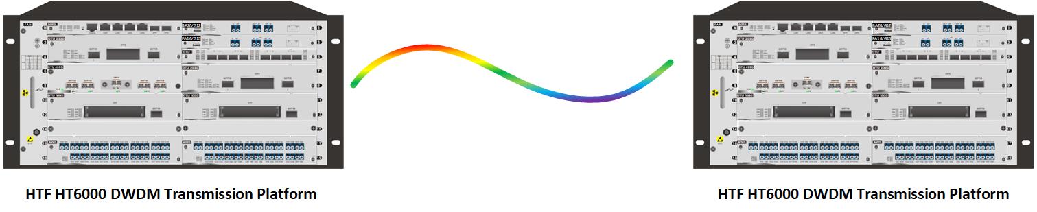
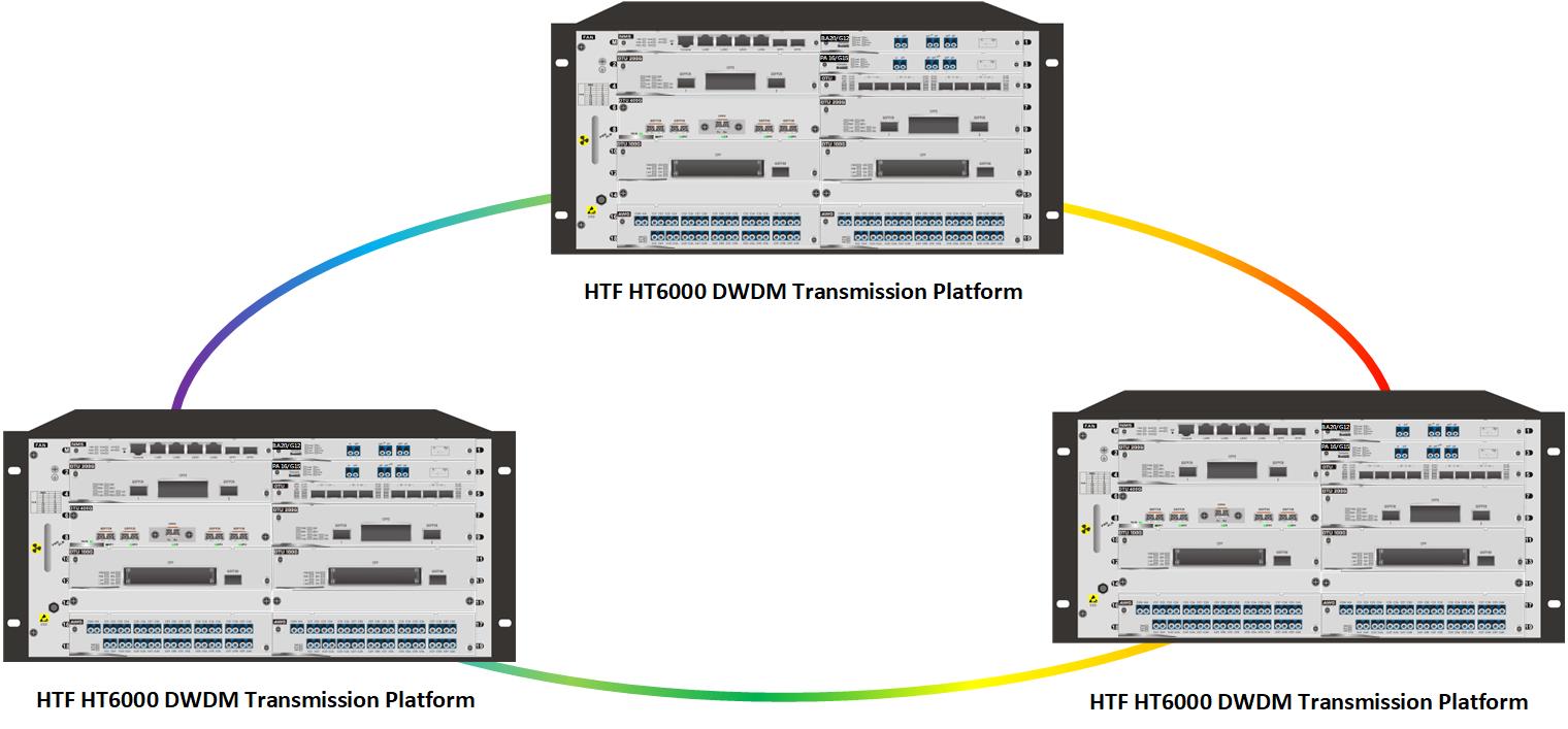
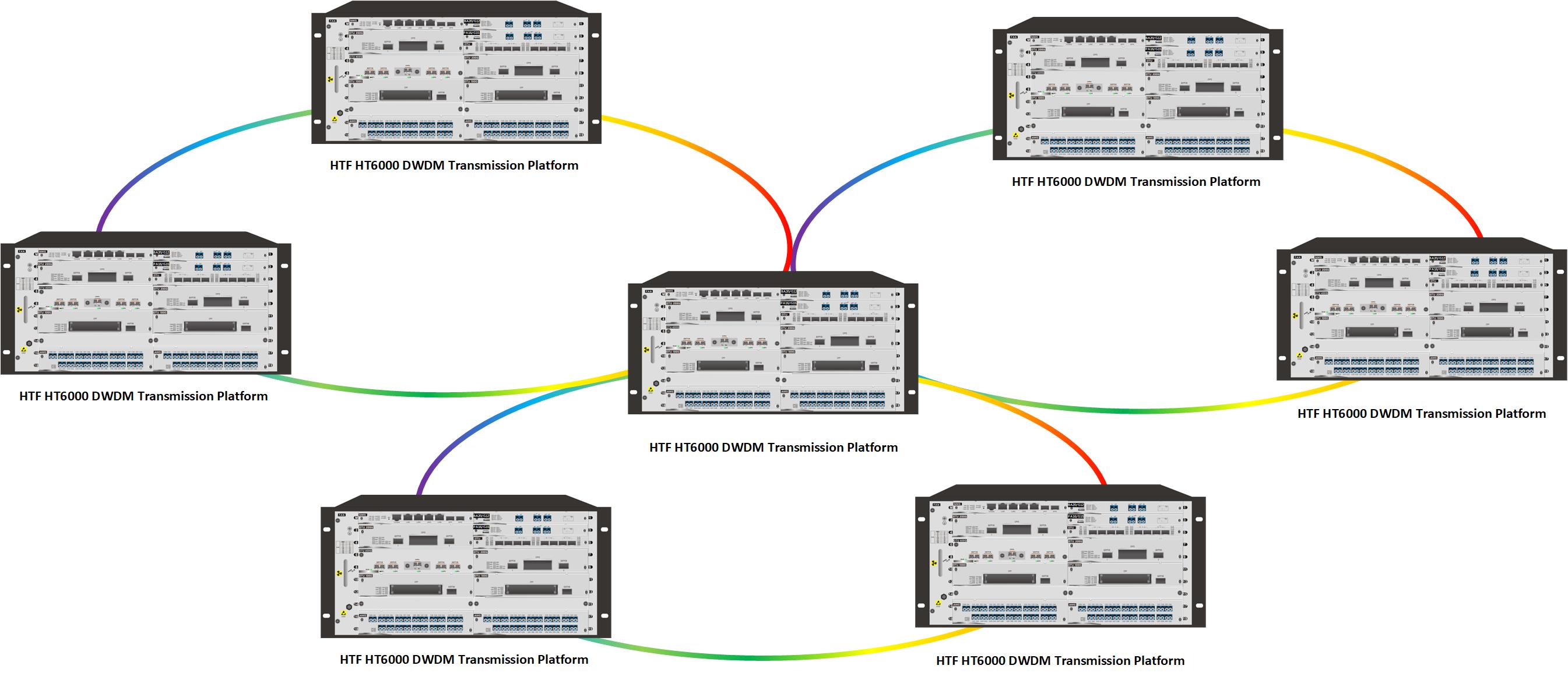
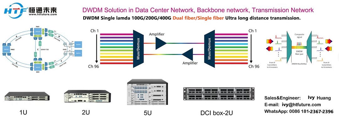
Point-to-point network, chain network, ring network, mesh network
Point-to-point line:referred to as P2P or PTP. Point-to-point transmission refers to the transmission of services between two points (data centers). Generally, it is optical transmission over a relatively short distance within 100 kilometers.
Chain network: There are one or more sites with business up and down between point-to-point transmission.
Ring network: all business sites form a ring network
Mesh network: transmission line composed of multiple interwoven ring networks.
HTF H6000 DWDM optical transmission platform can meet the needs of these 4 networks. If you want to know more, please feel free to consultIvy from HTF.
1.6T OSFP-XD DR8+ is designed to transmit and receive serial optical data links up to 212.5 Gb/s data rate (per channel) by PAM4 modulation format over single-mode fiber. It is a small-form- factor hot pluggable transceiver module integrated with high performance EML laser. It is compliant with 1600G Ethernet specs and OSFP-XD MSA.
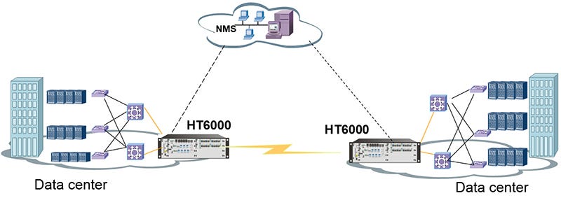
Internet giants, ICPs, and enterprises use DCI (Data Center Interconnect) solutions to provide high-quality and near-infinite bandwidth connections to their data centers, while controlling costs through self-built infrastructure. However, with the massive increase in the scale of data center construction, the demand for data center interconnection has doubled. How to make full use of the limited optical fiber resources and obtain reliable large-capacity transmission is one of the challenges of data center interconnection.
When building a DCI solution, what aspects need to be considered?
Not only need to consider the demand for connection bandwidth,
It is also necessary to consider the requirements of simplification of operation and maintenance and intelligence.
The DCI optical transmission equipment (HT6000) specially created by HTF for data center interconnection has the outstanding characteristics of large capacity, small size, low energy consumption, and simple operation and maintenance. The simplified management mode brings the ultimate user experience to the DCI bearer network.
HTF support customized DWDM Interconnect Solution for Data Center Cloud, If need the suitable solution for your Data Center, welcome to contact HTF team, Send your requirement to ivy@htfuture.com, Or Leave message or contact HTF sales online. Will reponse you within 24 hours.
HTF can help you design coherent 400G/200G/100G DWDM/OTN solution, DWDM Single lamda 100G/200G/400G Dual fiber/Single fiber Ultra long distance transmission. Expand your network capacity and 400G DCI network easily.
HTF can help you design coherent 400G/200G/100G DWDM/OTN solution, DWDM Single lamda 100G/200G/400G Dual fiber/Single fiber Ultra long distance transmission.
DWDM transceivers are available in different types, supporting transmission rate from 155 Mbit/s to 10 Gbit/s. Categorized by data rates and form factors, there are DWDM SFP transceiver, DWDM SFP+ transceiver, DWDM XFP transceiver, etc. as following.
Product Description DWDM SFP DWDM SFP transceivers provide a high-speed serial link at signaling rates from 100 Mbps to 2.5 Gbps. The DWDM SFP modules meet the requirements of the IEEE802.3 Gigabit Ethernet standard and ANSI Fibre Channel specifications, and are suitable for interconnections in Gigabit Ethernet and Fibre Channel environments.
DWDM XENPAK DWDM XENPAK is an important step in the evolution. It is the first 10GbE transceiver ever to support DWDM. DWDM XENPAK transceiver supports 32 different channels for up to 200 km with the aid of optical amplifiers known as EDFAs.
DWDM X2 DWDM X2 transceiver is a high performance, serial optical transponder module for high-speed, 10G data transmission applications. The optical module is fully compliant to IEEE 802.3ae standard for Ethernet, making it ideally suited for 10GbE datacom applications.
DWDM XFP DWDM XFP transceiver complies with the current XFP MSA specification. It supports SONET/SDH, 10GbE and 10-Gigabit Fibre Channel applications. It is small in size and cheap in price. DWDM SFP+ DWDM SFP+ is specifically designed for carriers and large enterprises that require a scalable, flexible, cost-effective network system. It is even smaller than the previous XFP and is the ideal choice for 10G highest-bandwidth application.
If need DWDM optical module, HTF can assist you to choose the suitable one.
HTF can help you design coherent 400G/200G/100G DWDM/OTN solution, DWDM Single lamda 100G/200G/400G Dual fiber/Single fiber Ultra long distance transmission.
Optical networking is a technology that uses optical signals to transmit data through fiber optic cables. It consists of a system of components including optical transmitters, optical amplifiers and fiber optic infrastructure to facilitate high-speed communications over long distances.
This technology supports the transmission of large amounts of data at high bandwidth, enabling faster and more efficient communications compared to traditional copper cable networks.
Main components of optical networks
The main components of an optical fiber network include optical fiber cables, optical transmitters, optical amplifiers, optical receivers, transceivers, wavelength division multiplexing (WDM), optical switches and routers, optical cross-connects (OXCS), and optical add-subtract multiplexers.
HTF can help you build and expand network capacity by DWDM equipment, support to design Single fiber or dual fiber 10G/100G/200G/400G transmission solution (40x200G). More details, welcome to contact HTF. ivy@htfuture.com Whatsapp/Wechat/Skype: +8618123672396
Hot pluggable QSFP28 MSA form factor Up to 80km reach for G.652 SMF with transport white box Single +3.3V power supply Temperature Range 0 to 85°C Transmitter: Cooled EML 2*27.5Gbaud/s DWDM TOSA Receiver: 2*27.5Gbaud/s Pin-PD ROSA 4*25G CAUI4 electrical interface Integrated SFEC with high coding gain PAM4 modulation format on 100GHz ITU DWDM wavelength grid compatible Dual CS adaptor Compatible with RoHS6
100Gbps PAM4 DWDM QSFP28 Application High bandwidth connectivity for Data Center Interconnection 100G Ethernet Metro-Access over DWDM P to P Access Network
The two channels of the transceiver meet above wavelength table. And other channel wavelength
configurations are acceptable for customize design.
All the specification is designed by single wavelength.
HTF also provide the Coherent 100G/200G/400G color DWDM transmission solution. Help you expand the network capacity easily. Any question, welcome to contact HTF. www.htfuture.com
CWDM used to be the popular choice in low capacity, short distance and low rate (up to 10G per wavelength) applications, as well as in networks where the initial requirement does not exceed 8 wavelengths. In addition, low cost entry point and the difference in economic scale make CWDM ideal for initial network set up. However, CWDM is limited as it cannot be amplified and does not support tunableDWDM 100G/200G/400G wavelengths. As the need for capacity grows, so does the demand to increase capacity by adding DWDM onto existing CWDM infrastructure. For more details, see DWDM overCWDM Network.
HTF support customized solution dwdm/cwdm/OTN solution design, 10G/100G/200G/400G dwdm , DCI-BOX, White box dwdm, help you expand network capacity easily.
The components of a traditional DWDM system consists of the transponder, multiplexer/de-multiplexer, optical add/drop multiplexers, and optical amplifiers.
DWDM components Below is a high level overview of the process in which data is transmitted using DWDM and what each component’s function is within the system: 1. The data stream comes in via the router and is input into the transponder. 2. The transponder maps the signal to a DWDM wavelength and sends it to the multiplexer (Mux) to consolidate the optical signal. 3. As the signal leaves the multiplexer, optical amplifiers boost the signal to allow the signal to travel over longer distances. 4. Along the way, optical add/drop multiplexers (OADM) can add and remove bitstreams of a specific wavelength. Also, additional amplifiers can be used to further boost the signal’s distance. 5. The signal the arrives and gets de-multiplexed (DeMux) into individual DWDM wavelengths, which are then passed through the transponder to be converted into the corresponding signals to be routed to its final destination.
HTF support customized solution design, 10G/100G/200G/400G dwdm , DCI-BOX, White box dwdm, help you expand network capacity easily.
Today we will talk about the application of wavelength division transmission equipment in data center computer rooms.
Foreword: HTF is the first choice for optical fiber expansion. We are a service provider with fifteen years of experience in the optical communication transmission industry, serving more than 1,000 industry customers, and providing customers with professional, stable and reliable optical transmission solutions — HTF.
Today we will talk about the application of wavelength division transmission equipment in data center computer rooms.
The Internet has developed rapidly in the past ten years, and various APP applications have emerged one after another. You can accomplish all kinds of unimaginable things without leaving home. If you don’t want to travel, you can see the scenery of Mount Everest online in real time through your mobile phone or TV at home. Doctors can Perform operations on patients thousands of miles away through remote control, or order takeout if you don’t want to and have steaming hot food delivered to you within half an hour. All these conveniences and high efficiency are inseparable from the support of the data center behind it.
Various apps, various softwares, or Internet technologies all need to be carried by hardware. Apps are carried by mobile phones, and public software services or cloud computing/big data/artificial intelligence/blockchain, etc. are carried by IT hardware. IT hardware all lives in a place called a data center.
Houses are for living in, but not necessarily for people to live in. A data center is a house specially used to house various IT equipment. The data center’s floor plans, wind, water, electricity, temperature and humidity, and fire and theft prevention are all designed to make the machines comfortable and machine-oriented.
Data centers are the infrastructure and real estate of the IT industry. The development of Internet technology has placed increasing demands on these infrastructures. The residents of the data center are servers, storage, switches and security equipment, etc., and the property management personnel are the operation and maintenance personnel of the data center. The data center provides computing or storage services to the outside world. Servers, PCs, smartphones, etc. also provide computing and storage services to the outside world, but the data center is larger and the shell is made of buildings instead of plastic. In fact, a data center is an oversized computer room with many servers dedicated to centralized management (storage, calculation, and exchange) of data. Data center, the English abbreviation is IDC, which is Internet Data Center.
One of the bandwidth costs of the data center is the cost of optical cable resources. The more optical fiber cores you rent, the more expensive it is. Wavelength division transmission equipment can be directly multiplexed and expanded on the original 2-core optical fiber, and the 2-core fiber can be transformed into 20-core, 40-core or even 80-core. . At present, most IDC customers already know that wavelength division can be used to solve the problem of insufficient optical cable resources.
2. Build a backbone network
Due to the large bandwidth of the upper backbone network of the data center, a single port exceeds 100G. If wavelength division equipment is used to build the network, a maximum bandwidth input of 80X100G/200G and a maximum of 16T can be achieved, which can meet the bandwidth output between cities, or between certain cities. Bandwidth entry and exit needs of some small countries.
3. Pure transparent transmission, low latency
Most of the customers in the data center have relatively high network requirements, such as bank customers, who have very high latency requirements. Since the wavelength division transmission equipment is purely transparent and does not perform any analysis and processing on the data, it only produces extremely low latency. When transmitting 100 kilometers, the delay is about 1 millisecond, so for high-end users in data centers, transmission equipment is a good choice.
4. Suitable for ultra-long distance transmission
Many data center services span multiple cities, and some even cross provinces and countries. The transmission distance is tens or hundreds of kilometers, or even thousands of kilometers. The longer the distance when laying optical cables, the higher the rental cost. At this time, the wave The transmission equipment can play its maximum value. The farthest ring network our transmission equipment has built overseas is more than 3,000 kilometers, surrounding the entire country and passing through more than 40 computer rooms. Currently, the equipment has been running stably for 6 For more than a year, users will need to upgrade and expand the wavelength division ports.
After talking so much, friends in the data center industry, do you want to buy this cost-effective 100G/200G/400G DWDM? Welcome to contact HTF, www.htfuture.comivy@htfuture.com +8618123672396
The OADM, or optical add drop multiplexer, is a gateway into and out of a single mode fiber. In practice, most signals pass through the device, but some would be “dropped” by splitting them from the line. Signals originating at that point can be “added” into the line and directed to another destination. An OADM may be considered to be a specific type of optical cross-connect, widely used in wavelength division multiplexing systems for multiplexing and routing fiber optic signals. They selectively add and drop individual or sets of wavelength channels from a dense wavelength division multiplexing (DWDM) multi-channel stream. OADMs are used to cost effectively access part of the bandwidth in the optical domain being passed through the in-line amplifiers with the minimum amount of electronics.
OADMs have passive and active modes depending on the wavelength. In passive OADM, the add and drop wavelengths are fixed beforehand while in dynamic mode, OADM can be set to any wavelength after installation. Passive OADM uses WDM filter, fiber gratings, and planar waveguides in networks with WDM systems. Dynamic OADM can select any wavelength by provisioning on demand without changing its physical configuration. It is also less expensive and more flexible than passive OADM. Dynamic OADM is separated into two generations.
A typical OADM consists of three stages: an optical demultiplexer, an optical multiplexer, and between them a method of reconfiguring the paths between the optical demultiplexer, the optical multiplexer and a set of ports for adding and dropping signals. The optical demultiplexer separates wavelengths in an input fiber onto ports. The reconfiguration can be achieved by a cross connection panel or by optical switches which direct the wavelengths to the optical multiplexer or to drop ports. The optical multiplexer multiplexes the wavelength channels that are to continue on from demultipexer ports with those from the add ports, onto a single output fiber.
Physically, there are several ways to realize an OADM. There are a variety of demultiplexer and multiplexer technologies including thin film filters, fiber Bragg gratings with optical circulators, free space grating devices and integrated planar arrayed waveguide gratings. The switching or reconfiguration functions range from the manual fiber patch panel to a variety of switching technologies including microelectromechanical systems (MEMS), liquid crystal and thermo-optic switches in planar waveguide circuits.
CWDM and DWDM OADM provide data access for intermediate network devices along a shared optical media network path. Regardless of the network topology, OADM access points allow design flexibility to communicate to locations along the fiber path. CWDM OADM provides the ability to add or drop a single wavelength or multi-wavelengths from a fully multiplexed optical signal. This permits intermediate locations between remote sites to access the common, point-to-point fiber message linking them. Wavelengths not dropped, pass-through the OADM and keep on in the direction of the remote site. Additional selected wavelengths can be added or dropped by successive OADMS as needed.
HTFuture provides a wide selection of specialized OADMs for WDM system. Custom WDM solutions are also available for applications beyond the current product designs including mixed combinations of CWDM and DWDM.
HTFuture aim to be your Reliable Partner for different kinds of Compatible transceiver (QSFP28, QSFP+, SFP, XFP, SFP+ etc) | OTN optical transmission system|DWDM Mux Demux|OADM | OTU | EDFA | NMS | DCM | OLP | OBP etc| More information, welcome to contact Ivy, contact Ivy. Email: sales6@htfuture.com Skype: live:sales6_1683
Transmission distance has always been a key factor during deployment of fiber optic network. DWDM technologies, which are considered as the most cost-effective ways to increase the network capacity over long transmission distance, have been widely applied in our telecommunication network. To further extend transmission distance of optical signals transmission from the DWDM fiber optic transceivers, optical amplifiers are usually used in the DWDM network. Different types of optical amplifiers have been invented to meet the signal amplifying requirements at different situations. This post will introduce the differences between the three most commonly used optical amplifier: pre-amplifier, booster amplifier and in-line amplifier.
Basics of Optical Amplifier
In the past, if you want to extend the transmission distance of DWDM network, optical regenerator station is required to be installed in the fiber link every 80km to 100km. The regenerator station will electronically regenerate the optical signals to overcome the power loss and ensure that the optical signal can be detected at the receiver end. However, this requires a lot of money and is not easy to upgrade the whole network.
With optical amplifier, things become much easier. The optical amplifier can enlarge the optical signals without the regeneration. In addition, the network upgrading is more cost-effective with optical amplifier. Each optical amplifier has an important factor which is operation gain measured in dB. The operation gain of the optical amplifier should be carefully calculated to ensure the network performance. Pre-amplifier, booster amplifier and in-line amplifier are used in different places in the fiber optic network. And they support different operation gain according to the whole network requirement.
Pre-Amplifier, Booster Amplifier and In-line Amplifier
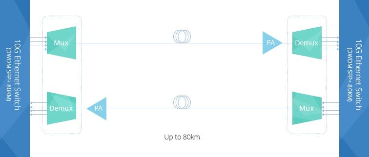
Pre-Amplifier is usually installed at the receiver end of the DWDM network to amplify the optical signal to the required level to ensure that it can be detected by the receiver. The following picture shows a typical diagram for a duplex 10G DWDM network which can support 80km. A pre-amplifier is installed at each receiving end of this network. There will be great power loss after the optical signal goes through the 80km optical fiber. Then, pre-amplifier installed at the receiver end is necessary. Generally, a pre-amplifier should offer high gain to ensure that the optical signal is detectable.
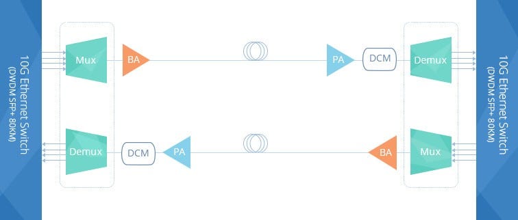
Booster Amplifier is installed in the transmitting end of the fiber optic network, which can amplifier the amplify the optical signal launched into the fiber link. It is usually used in DWDM network where the multiplexer attenuates the signal channels. The following picture shows a 10G DWDM network using booster amplifier (BA) at the transmitting end and pre-amplifier (PA) at receiving end. Thus, this 10G DWDM network can support a transmission distance much longer than the above mentioned one. Please note, a DCM (Dispersion Compensation Module) is added in this network to further ensure the transmission quality. A booster amplifier usually provides low gain and high output power.
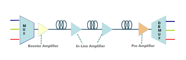
In-line Amplifier is easy to understand. The gain provided by the pre-amplifier and booster amplifier might not be enough due to the optical loss caused by long haul transmission. In-line amplifier is installed in the fiber optic link every 80–100km as shown in the following picture. It has moderate gain and has similar output power to those of booster amplifier.
Conclusion
Optical amplifier can help to amplifier the optical power during long haul transmission to ensure that the receiver can detect the optical signal without error. Three amplifiers are commonly used in DWDM network. Booster amplifier is used to amplifier optical power at the transmitting end and pre-amplifier is placed at the receiver end. If the transmission distance is longer than 150km or have great power loss during transmission, in-line amplifier is suggested to be installed every 80km to 100k in the fiber optic link. The gain of these amplifiers should be carefully calculated during practical use. Kindly visit DWDM EDFA Amplifier page for more details.
HTFuture aim to be your Reliable Partner for different kinds of Compatible transceiver (QSFP28, QSFP+, SFP, XFP, SFP+ etc) | OTN optical transmission system|DWDM Mux Demux|OADM | OTU | EDFA | NMS | DCM | OLP | OBP etc| More information, welcome to contact Ivy, contact Ivy. Email: sales6@htfuture.com Skype: live:sales6_1683