显示标签为“HTF”的博文。显示所有博文

2019年8月11日星期日

WDM-PON Network: An Efficient Solution for 5G Deployment

Driven by the rapid development of mobile communication industry, 5G network has boomed. However, 5G also faces some challenges such as the higher transmission bandwidth requirement. How to solve these problems? The WDM-PON network may be a better solution. This post will explain the advantages of WDM-PON technology and how it helps the 5G deployment.

Overview of WDM-PON Network & 5G

As it’s known to all, WDM-PON (Wavelength Division Multiplexing-Passive Optical Network) combines WDM technology with PON topology structure that allows operators to deliver high bandwidth to multiple endpoints over long distances. It includes some technologies, including colorless ONU technology, Auxiliary Management and Control Channel (AMCC), optical modules, OAM, and protection switching. With these key technologies, WDM-PON is regarded as an ideal solution which can meet the 5G requirements and has attracted great attention nowadays.
5G stands for the fifth generation of the wireless mobile network. It will be built on the foundation created by 4G LTE to allow people to send texts, make calls, and browse the web, etc. These upgraded 5G performance targets contain higher data rate, energy saving, higher-quality and massive device connectivity.

5G network

Why Choose WDM-PON for 5G Deployment?

As mentioned above, WDM-PON owns some useful technologies, which have unique advantages in 5G applications, including high bandwidth, low latency, low costs, fiber savings, easy maintenance, etc. The following will focus on introducing some of its merits.

High Bandwidth

The WDM-PON technology allows for traffic separation within the same physical fiber by different wavelengths. This results in a network that provides logical point-to-point connections over physical point-to-multipoint network topology. Moreover, AMCC signal modulation helps stack a management channel onto each wavelength. Therefore, the solution for carrying 5G front-haul over WDM-PON can offer a dedicated wavelength and extensive bandwidth resources to each user, saves time and increases transmission efficiency.

Low Latency

Having AMCC technology to deploy 5G, there is no need to use frame processing or dynamic bandwidth allocation (DBA) scheduling. This architecture provides low latency, low-frequency jitter, and flexible configuration of different front-haul interfaces.

Low Costs

With PON topology, it reduces the number of fiber needed by 5G front-haul networks with high site densities. The existing fiber infrastructure and equipment room are utilized, which saves the deployment and maintenance costs. What’s more, WDM-PON carries out an integrated front-haul/middle-haul (XHaul) transport network with the OLT. This OLT platform and the DU pool can be deployed in the same equipment room, which reduces the equipment construction costs. In addition, using the colorless technology of ONU in WDM-PON system results in low costs.

WDM-PON Network for 5G Deployment

Unlike the 4G which has the BBU and RRU two-level architectures, the 5G is constructed as three entities: CU (Centralized Unit), DU (Distribute Unit) and AAU (Active Antenna Unit). And 5G has three application scenario, including front-haul, middle-haul, and back-haul transmission. In the 5G Front-haul network, WDM-PON can be an efficient solution.

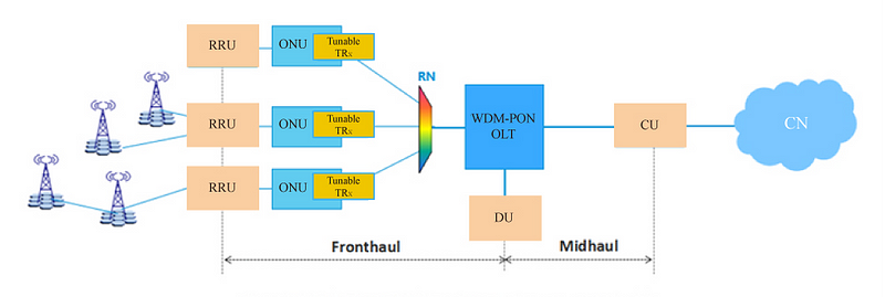
The following figure 1 shows the architecture of WDM-PON 5G front-haul network. Several RRUs and a DU are connected through a WDM-PON point-to-multipoint topology. The WDM-PON OLT is connected to the DU, CU, and ONU. ONU is also connected to RRUs. This OLT platform carries the front-haul traffic between the DU and RRUs as well as the middle-haul traffic between the DU and CU. In terms of the front-haul transmission or the connection between RRUs and DU, WDM-PON transmission interfaces play a significant role that enables the transparent user data transmission between them. In addition, the solution of applying WDM-PON to carry 5G is especially suitable for those operators who have to provide both wireless and wireline services in a greenfield scenario.

WDM-PON network

Summary

As boasting these advantages such as high capacity, low latency, cost-saving, etc., WDM-PON network is considered as an important solution for 5G. And the use of WDM-PON technology would become very common. To pave the way for the upcoming 5G network, HTFuture is striving to be the innovator in 5G communication. In fact, HTFuture has developed optical transceiver modules for WDM-PON network such as DWDM SFP+. If you have any needs, welcome to visit www.htfuture.com

HTFuture aim to be your Reliable Partner for different kinds of Compatible transceiver (QSFP28, QSFP+, SFP, XFP, SFP+, PON, Tunable, Copper, BIDI etc) | OTN optical transmission system|DWDM Mux Demux|OADM | OTU | EDFA | NMS | DCM | OLP | OBP etc| More information, welcome to contact Ivy, contact Ivy. Email: sales6@htfuture.com Skype: live:sales6_1683

HTFuture team are ready and happy to assist you.

2019年8月9日星期五

What are the differences between GPON, XG-PON and XGS-PON?

Specification Differences Between 10G GPON and GPON

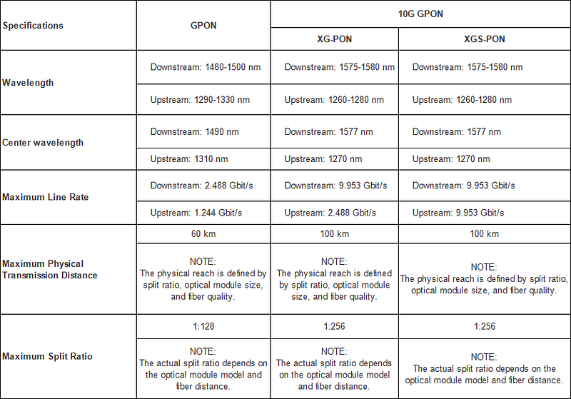
XG-PON, 10-Gigabit-capable passive optical network, provides asymmetric 10G transmission (Maximum downstream line rate: 9.953 Gbit/s, Maximum upstream line rate: 2.488 Gbit/s ).

XGS-PON, 10-Gigabit-capable symmetric passive optical network, provides symmetric 10G transmission (Maximum downstream line rate: 9.953 Gbit/s, Maximum upstream line rate: 9.953 Gbit/s ).

The following table lists specification differences between the two technologies.
HTFuture aim to be your Reliable Partner for different kinds of Compatible transceiver (QSFP28, QSFP+, SFP, XFP, SFP+, PON, Tunable, Copper, BIDI etc) | OTN optical transmission system|DWDM Mux Demux|OADM | OTU | EDFA | NMS | DCM | OLP | OBP etc| 

More information, welcome to contact Ivy, contact Ivy. Email: sales6@htfuture.com Skype: live:sales6_1683

HTFuture team are ready and happy to assist you.

2019年8月8日星期四

Overview of PON Network

PON has now became a popular network technology all over the globe. It first came in to being in 1995. The International Telecommunication Union (ITU) standardized two initial generations of PON — APON and BPON. And the advancement of PON network has never stopped. Until now, the recent PON standard of NG-PON2 has been put forward in 2015. With the maturity of PON, people are more easily accessible to networks today. But what does PON exactly mean?

 What’s the composition of PON network? The following part will give you the answer.
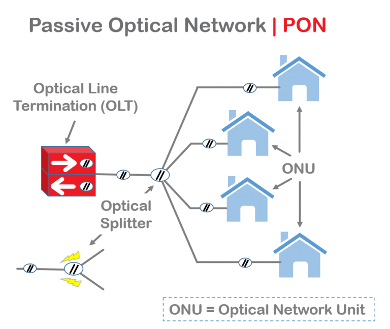
PON, also known as passive optical network, is a technology in telecommunication that implements a point-to-multipoint (P2MP) architecture. Unpowered fiber optic splitters are used to enable a single optical fiber to serve multiple end-points such as customers instead of providing individual fibers between the central office (hub) and customer. According to different terminations of PON, the network system can be divided into fiber-to-the-home (FTTH), fiber-to-the-curb (FTTC), fiber-to-the-curb (FTTB), etc. To be specific, a PON is made up of an optical line terminal (OLT) at the service provider’s hub and a number of optical network units (ONUs) or optical network terminals (ONTs) near end users. And “passive” is just used to describe that no power requirement or active electronic component is included for transmitting signals in the system.
Types of PON Network

Here are some types of PON that have been used throughout the years:

1) APON

Its full name is asynchronous transfer mode (ATM) passive optical network. As the original PON system, APON uses ATM technology to transfer data in packets or cells of a fixed size. In APON, downstream transmission is a continuous ATM stream at a bit rate of 155 Mbps or 622 Mbps. Upstream transmission is in the form of bursts of ATM cells at 155 Mbps.

2) BPON

BPON, also known as broadband PON, is the improved version of APON. It adopts wavelength division multiplexing (WDM) for downstream transmission with the transmission rate up to 622 Mbps. It also provides multiple broadband services such as ATM, Ethernet access and video distribution. Today, BPON is more popular than APON.

3) EPON

EPON or Ethernet PON uses the Ethernet packets instead of ATM cells. Upstream and downstream rates of EPON are able to achieve up to 10 Gbps. It is now widely applied to FTTP or FTTH architecture to serve multiple users. With the advantages of scalability, simplicity, multicast convenience and capability of providing full service access, many Asian areas adopt EPON for their networks.

4) GPON

Gigabit PON is the development of BPON. It supports various transmission rates with the same protocol. The maximum data rate of downstream is 2.5 Gbps and upstream is 1.25 Gbps. It is also widely used for FTTH networks. But compared with EPON, its burst sizes and physical layer overhead are smaller.

Advantages of PON
  • Low cost, simple maintenance, flexible extensibility and easy to upgrade. And no need for power during transmission saves a lot for long-term management.
  • Using pure media network avoids the interference of lightning and electromagnetism. Thus PON network is suitable for areas under harsh conditions.
  • Low occupancy of central office resources, low initial investment and high rate of return.
  • As the P2MP network, PON is able to provide a large range of service to plenty of users.
Conclusion

PON network is for sure an effective solution for multiple network users. EPON and GPON are the most commonly deployed PON systems at present. Since people have been seeking for higher bandwidth provisioning, the capability of transmission will be greatly improved in the near future.
HTFuture aim to be your Reliable Partner for different kinds of Compatible transceiver (QSFP28, QSFP+, SFP, XFP, SFP+ etc) | OTN optical transmission system|DWDM Mux Demux|OADM | OTU | EDFA | NMS | DCM | OLP | OBP etc| More information, welcome to contact Ivy, contact Ivy. Email: sales6@htfuture.com Skype: live:sales6_1683
HTFuture team are ready and happy to assist you.

2019年8月1日星期四

How Much Do You Know About OADM

The OADM, or optical add drop multiplexer, is a gateway into and out of a single mode fiber. In practice, most signals pass through the device, but some would be “dropped” by splitting them from the line. Signals originating at that point can be “added” into the line and directed to another destination. An OADM may be considered to be a specific type of optical cross-connect, widely used in wavelength division multiplexing systems for multiplexing and routing fiber optic signals. They selectively add and drop individual or sets of wavelength channels from a dense wavelength division multiplexing (DWDM) multi-channel stream. OADMs are used to cost effectively access part of the bandwidth in the optical domain being passed through the in-line amplifiers with the minimum amount of electronics.

OADMs have passive and active modes depending on the wavelength. In passive OADM, the add and drop wavelengths are fixed beforehand while in dynamic mode, OADM can be set to any wavelength after installation. Passive OADM uses WDM filter, fiber gratings, and planar waveguides in networks with WDM systems. Dynamic OADM can select any wavelength by provisioning on demand without changing its physical configuration. It is also less expensive and more flexible than passive OADM. Dynamic OADM is separated into two generations.
A typical OADM consists of three stages: an optical demultiplexer, an optical multiplexer, and between them a method of reconfiguring the paths between the optical demultiplexer, the optical multiplexer and a set of ports for adding and dropping signals. The optical demultiplexer separates wavelengths in an input fiber onto ports. The reconfiguration can be achieved by a cross connection panel or by optical switches which direct the wavelengths to the optical multiplexer or to drop ports. The optical multiplexer multiplexes the wavelength channels that are to continue on from demultipexer ports with those from the add ports, onto a single output fiber.

Physically, there are several ways to realize an OADM. There are a variety of demultiplexer and multiplexer technologies including thin film filters, fiber Bragg gratings with optical circulators, free space grating devices and integrated planar arrayed waveguide gratings. The switching or reconfiguration functions range from the manual fiber patch panel to a variety of switching technologies including microelectromechanical systems (MEMS), liquid crystal and thermo-optic switches in planar waveguide circuits.

CWDM and DWDM OADM provide data access for intermediate network devices along a shared optical media network path. Regardless of the network topology, OADM access points allow design flexibility to communicate to locations along the fiber path. CWDM OADM provides the ability to add or drop a single wavelength or multi-wavelengths from a fully multiplexed optical signal. This permits intermediate locations between remote sites to access the common, point-to-point fiber message linking them. Wavelengths not dropped, pass-through the OADM and keep on in the direction of the remote site. Additional selected wavelengths can be added or dropped by successive OADMS as needed.

HTFuture provides a wide selection of specialized OADMs for WDM system. Custom WDM solutions are also available for applications beyond the current product designs including mixed combinations of CWDM and DWDM.

HTFuture aim to be your Reliable Partner for different kinds of Compatible transceiver (QSFP28, QSFP+, SFP, XFP, SFP+ etc) | OTN optical transmission system|DWDM Mux Demux|OADM | OTU | EDFA | NMS | DCM | OLP | OBP etc| More information, welcome to contact Ivy, contact Ivy. Email: sales6@htfuture.com Skype: live:sales6_1683
HTFuture team are ready and happy to assist you.

2019年7月29日星期一

Differences Between Pre-Amplifier, Booster Amplifier and In-line Amplifier

Transmission distance has always been a key factor during deployment of fiber optic network. DWDM technologies, which are considered as the most cost-effective ways to increase the network capacity over long transmission distance, have been widely applied in our telecommunication network. To further extend transmission distance of optical signals transmission from the DWDM fiber optic transceivers, optical amplifiers are usually used in the DWDM network. Different types of optical amplifiers have been invented to meet the signal amplifying requirements at different situations. This post will introduce the differences between the three most commonly used optical amplifier: pre-amplifier, booster amplifier and in-line amplifier.

Basics of Optical Amplifier

In the past, if you want to extend the transmission distance of DWDM network, optical regenerator station is required to be installed in the fiber link every 80km to 100km. The regenerator station will electronically regenerate the optical signals to overcome the power loss and ensure that the optical signal can be detected at the receiver end. However, this requires a lot of money and is not easy to upgrade the whole network.

With optical amplifier, things become much easier. The optical amplifier can enlarge the optical signals without the regeneration. In addition, the network upgrading is more cost-effective with optical amplifier. Each optical amplifier has an important factor which is operation gain measured in dB. The operation gain of the optical amplifier should be carefully calculated to ensure the network performance. Pre-amplifier, booster amplifier and in-line amplifier are used in different places in the fiber optic network. And they support different operation gain according to the whole network requirement.

Pre-Amplifier, Booster Amplifier and In-line Amplifier

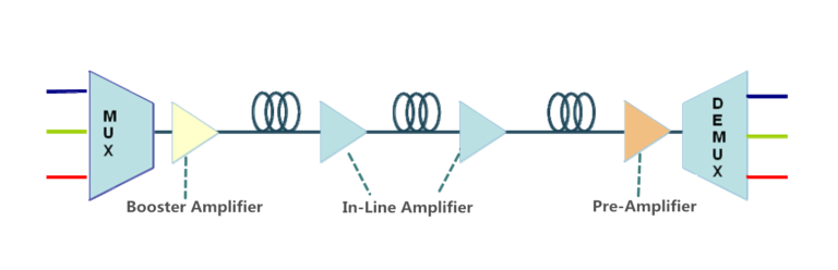
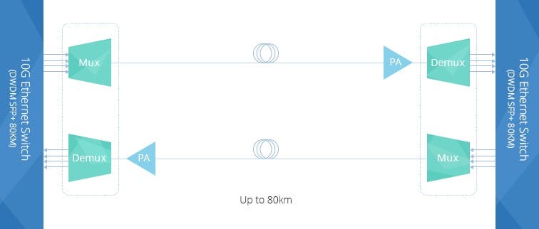
Pre-Amplifier is usually installed at the receiver end of the DWDM network to amplify the optical signal to the required level to ensure that it can be detected by the receiver. The following picture shows a typical diagram for a duplex 10G DWDM network which can support 80km. A pre-amplifier is installed at each receiving end of this network. There will be great power loss after the optical signal goes through the 80km optical fiber. Then, pre-amplifier installed at the receiver end is necessary. Generally, a pre-amplifier should offer high gain to ensure that the optical signal is detectable.

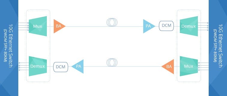
Booster Amplifier is installed in the transmitting end of the fiber optic network, which can amplifier the amplify the optical signal launched into the fiber link. It is usually used in DWDM network where the multiplexer attenuates the signal channels. The following picture shows a 10G DWDM network using booster amplifier (BA) at the transmitting end and pre-amplifier (PA) at receiving end. Thus, this 10G DWDM network can support a transmission distance much longer than the above mentioned one. Please note, a DCM (Dispersion Compensation Module) is added in this network to further ensure the transmission quality. A booster amplifier usually provides low gain and high output power.
In-line Amplifier is easy to understand. The gain provided by the pre-amplifier and booster amplifier might not be enough due to the optical loss caused by long haul transmission. In-line amplifier is installed in the fiber optic link every 80–100km as shown in the following picture. It has moderate gain and has similar output power to those of booster amplifier.
Conclusion

Optical amplifier can help to amplifier the optical power during long haul transmission to ensure that the receiver can detect the optical signal without error. Three amplifiers are commonly used in DWDM network. Booster amplifier is used to amplifier optical power at the transmitting end and pre-amplifier is placed at the receiver end. If the transmission distance is longer than 150km or have great power loss during transmission, in-line amplifier is suggested to be installed every 80km to 100k in the fiber optic link. The gain of these amplifiers should be carefully calculated during practical use. Kindly visit DWDM EDFA Amplifier page for more details.

HTFuture aim to be your Reliable Partner for different kinds of Compatible transceiver (QSFP28, QSFP+, SFP, XFP, SFP+ etc) | OTN optical transmission system|DWDM Mux Demux|OADM | OTU | EDFA | NMS | DCM | OLP | OBP etc| More information, welcome to contact Ivy, contact Ivy. Email: sales6@htfuture.com Skype: live:sales6_1683
HTFuture team are ready and happy to assist you.

2019年7月11日星期四

How to Select Direct Attach Cable?

In today’s telecommunication market, high-qualified cables are always sought by users to satisfy the increasing demands of greater bandwidth and the growing amount of data transmission. As a result, direct attach cables have been designed to meet these requirements. Maybe you are not familiar with them and can’t determine which kind of direct attach cable is applicable for your networking servers. There is no need to worry. This post will introduce direct attach cables in details.

Definition of Direct Attach Cable

Direct attach cable (DAC), a kind of optical transceiver assembly, is a form of high speed cable with “transceivers” on either end used to connect switches to routers or servers. DACs are much cheaper than the regular optics, since the “transceivers” on both ends of DACs are not real optics and their components are without optical lasers. In storage area network, data center, and high-performance computing connectivity, they are preferable choice for their low cost, low power consumption and high performances.

Classifications of Direct Attach Cable

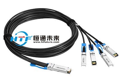
Direct attach cables can be divided into several types according to different standards. By Ethernet transmission rate and construction standard, 10G SFP+ cables, 40G QSFP+ cables, and 120G CXP cables are available. Classification according to the number of connectors is also feasible. Most DAC assemblies have one connector on each end of the cable, but there is a special kind of DAC assembly which may have 3 or 4 connectors on one end of the cable. Take QSFP+ to 4 SFP+ Passive Copper Direct Attach Breakout Cable for example, it features a single QSFP+ connector (SFF-8436) rated for 40-Gb/s on one end and 4 SFP+ connectors (SFF-8431), each rated for 10-Gb/s, on the other.
Based on material of cables used, there are direct attach copper cables and active optical cables.

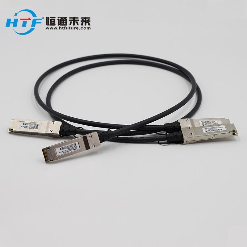
Direct Attach Copper Cable — Direct attach copper cables are designed in either active or passive versions. The former provides signal processing electronics to avoid signal issue, thus to improve signal quality. What’s more, the former can transmit data over a longer distance than the latter which offers a direct electrical connection between corresponding cable ends. Nowadays, direct attach copper cables still have a place in market owing to their interchangeability, low cost and various data rates.

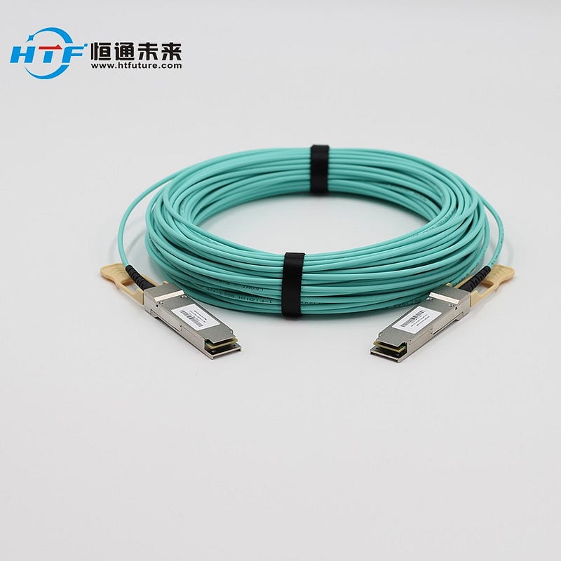
Active Optical Cable — Active optical cable (AOC) is one form of DAC. It integrates multi-mode optical fiber, fiber optic transceivers, control chip and modules. It uses electrical-to-optical conversion on the cable ends to improve speed and distance performance of the cable while mating with electrical interface standard. Compared with direct attach copper cable, its smaller size, electromagnetic interference immunity, lower interconnection loss and longer transmission distance make it popular among consumers.

Direct attach cables allow for greater bandwidth cost-effectively. As for which kind or kinds of DACs are suitable for network connectivity, it depends on specific situations. HTFuture supplies above-mentioned high-qualified DACs. Also, DACs can be customized in HTFuture to meet your different requirements.

More information about DACs, Welcome to conatct Ivy from HTFuture:
Email: sales6@htfuture.com Skype: live:sales6_1683
HTFuture team are ready and happy to assist you.


2019年7月4日星期四

CWDM Network: Technology Overview and Common Applications

Fiber exhaust is an inevitable problem constantly faced by carriers since the demand for higher speed bandwidth never ceases. The ever-improving wavelength division multiplexing (WDM) technology nowadays is increasingly used to boost network capacity, enabling carriers to deliver more services over their existing fiber infrastructure. CWDM, as one form of the mature WDM technologies, is a perfect fit for access networks and metro/regional networks. This article addresses the CWDM fundamentals and its common applications, and how CWDM helps to maximize network capacity effectively.

CWDM Technology at a Glance

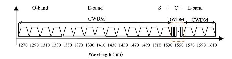
Coarse wavelength division multiplexing (CWDM) came into prominence as a cost-effective alternative to maximize network capacity in the access, metro and regional network segments. It gains in more popularity in area with a relatively moderate traffic growth due to its simple deployment and low cost. ITU-T G.694.2 defines 18 wavelengths for CWDM transport ranging from 1270 to 1610 nm, spaced at 20 nm apart. But 8 wavelength in the 1470–1610nm band is mostly used since there exist high attenuation in the 1270–1450 nm band. This technology shines out in access network deployments by obtaining the advantages of flexible add-drop capacity and network design simplicity.


Common Applications of CWDM

After going through the basics of CWDM technology, this section will further explain its common applications. CWDM is primarily deployed in two areas: metropolitan and access networks. Let’s see how they could benefit from applying it.

Fiber Exhaust Relief

Fiber exhaust appears to be a severe problem that carriers endeavor to solve, especially for some metropolitan networks where data traffic increases continuously. Adding CWDM to the original optical network presents a cost-efficient and simple approach to this problem. In this case, carriers can add new services over a existing single optical fiber, while not interrupting service for existing customers. This solution is ideally suited for carriers that desires to increase the already installed network capacity without new fiber construction.


Enterprise LAN and SAN Connection

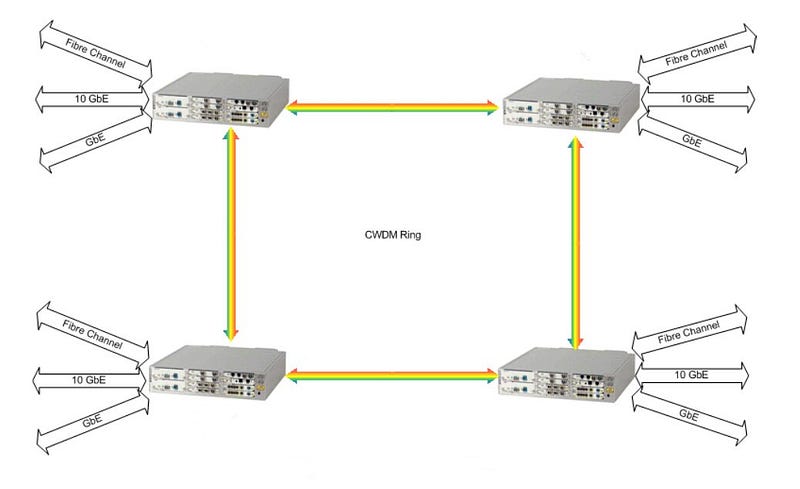
When interconnecting geographically dispersed Local Area Networks (LANs) and Storage Area Networks (SANs), CWDM rings and point-to-point links offer an optimum option. It is beneficial to integrate multiple Gigabit Ethernet, 10 Gigabit Ethernet and Fiber Channel links over a single fiber for CWDM point-to-point applications or for ring applications.


Adoption in Metro Networks With Lower Cost

4 channel CWDM system offers an ideal solution for smaller metro/regional markets which demand for moderate traffic growth. This configuration can expand the available capacity four times over an existing network, enabling less deployment cost than the commonly adopted 8 channel system. Meanwhile, the scalability of this 4 channel system also allows carriers to upgrade to 8 channel systems when the need occurs.

Central Office to Customer Premise Interconnection

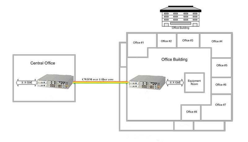
Coarse WDM system is also well-fitted for metro-access applications such as Fiber to the Building (FTTB). Let’s take the most widely used 8 channel CWDM network for example, it is capable of delivering 8 independent wavelength services from the Central Office (CO) to multiple business offices located in the same building.


Combining With PON

Passive Optical Network (PON) is a point-to-multipoint optical network to deliver bandwidth to the last mile. It is cost-effective because it uses passive devices (splitters for example) instead of expensive active electronics. The issue exists in PON is that the amount of bandwidth they can support is rather limited. Since CWDM serves to multiple bandwidth, when combining it with PON, each additional lambda becomes a virtual point-to-point connection from a central office to an end user. If one end user in the original PON deployment needs his own fiber, adding CWDM to the PON fiber creates a virtual fiber for that user. Once the traffic is switched to the assigned lambda, the bandwidth taken from the PON is now available for other end users, so the access system can maximize fiber efficiency.

Conclusion

CWDM has clearly become the preferred method for increasing the bandwidth of metro/regional and optical access networks quickly, simply and at lowest cost. And it has proven to be sufficiently robust and reliable for upgrading the optical network to accommodate future growth. Hope this article could help to get a better understanding of coarse WDM technology.

HTFuture can provide you the full range of CWDM DWDM products that you need. If there is any inquiry, just let me know please.

Ivy: sales6@htfuture.com Skype: live:sales6_1683

HTFuture team are ready and happy to assist you.
2019年5月9日星期四

EPON vs GPON Standard

EPON, based on Ethernet technology, is compliant with the IEEE 802.3ah (mid-2004) Ethernet in the First Mile standard that is now merged into the IEEE Standard 802.3–2005. It is a solution for the “first mile” optical access network. While GPON, or Gigabit PON, is expected to prevail as a leading optical access technology and to eliminate the bandwidth bottleneck in the last mile. Its requirements were set to force by the Full-Service Access Network (FASN) group, which was later adopted by ITU-T as the G.984.x standards.

EPON vs GPON Data Rate

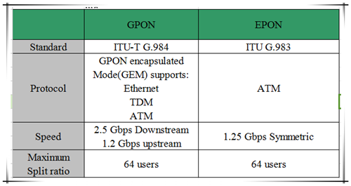
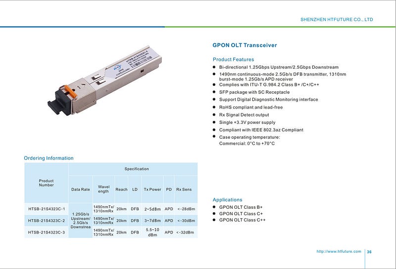
In EPON, both downstream and upstream line rates are 1.25 Gbps, but due to the 8B/10B line encoding, the bit rate for data transmission is 1 Gbps. GPON, on the other hand, supports an asymmetrical data rate of 1.25 Gbps in both streams, as well as a data rate of 2.5 Gbps in downstream and a data rate of 1.25 Gbps in upstream. Hence GPON is better than EPON in this aspect. The following table has a brief comparison of GPON and EPON technology in the PON upstream and downstream bandwidth, bandwidth efficiency and the transmission.
EPON vs GPON Layering

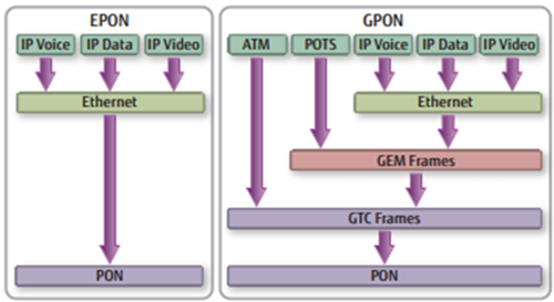
Besides the above characteristics, perhaps the most striking distinction between the two protocols is a marked difference in the architectural approach, especially in layering. The image below will help you to figure it out.
In EPON, Ethernet frames are carried in their native format on the PON, which greatly simplifies the layering model and the associated management. EPON employs a single layer that uses IP (Internet Protocol) to carry data, voice, and video.

GPON, on the other hand, supports two layers of encapsulation. First, TDM (Time Division Multiplexing) and Ethernet frames are wrapped into GEM (GPON Encapsulation Mode) frames, which have a GFP-like format (derived from Generic Frame Procedure ITU G.7401). Secondly, ATM (Asynchronous Transfer Mode) and GEM frames are both encapsulated into GTC (GPON Transmission Convergence) frames that are finally transported over the PON.

The main purpose of the GEM frame is to provide a frame-oriented service, as an alternative to ATM, in order to efficiently accommodate Ethernet and TDM frames. With GEM, all traffic is mapped across the GPON network using a variant of SONET/SDH GFP. GEM supports a native transport of voice, video, and data without an added ATM or IP encapsulation layer. That’s why GPON supports downstream rates as high as 2.5 Gbps and upstream rates from 155 Mbps to 2.5 Gbps. It is much faster than EPON. However, EPON clearly offers a much simpler and more straightforward solution than GPON. The support of ATM and the double encapsulation of GPON serve no real benefit over a pure Ethernet transport scheme.

Cost Comparison

The use of EPON allows carriers to eliminate complex and expensive ATM and Sonet elements and to simplify their networks, thereby lowering costs to subscribers. Currently, EPON equipment costs are approximately 10 percent of the costs of GPON equipment, and EPON equipment is rapidly becoming cost competitive with VDSL.

Summary

It is hard to say GPON is better than EPON, or vice verse. They each have their merits and demerits. When it comes to certain IP/Ethernet services, EPON is more suitable and cost-effective. While GPON has its own advantages in higher bandwidth, faster transmission rate and supporting triple-play services. Until now, EPON is still the mainstream of PON, especially in the Asian countries, but GPON is expanding quickly lately.
If need more information, feel free contact Ivy from HTFuture: sales6@htfuture.com, HTFuture team are ready and happy to assist you.
Which thing need consider when deploy 400G between data center distance in 120KM?

  In an era characterized by explosive data growth and the relentless expansion of cloud computing services, the demand for high - speed and...