Network expansion spurs the demand for faster data transmission and higher capacity over the network. In this case, DWDM emerges as a cost-effective solution to handle these issues, working efficiently to combine multiple wavelengths together and sent them over one single fiber. With the ability to carry up to 140 channels theoretically, higher capacity can be achieved by DWDM technology. This article guides you through some basics of DWDM topology.
Common DWDM Topology Overview
DWDM networks are grouped into four major topological configurations: DWDM point-to-point with or without add-drop multiplexing network, fully connected mesh network, star network, and DWDM ring network with OADM nodes and a hub. The requirements of each DWDM topology differ, and based on various application, it may involve different optical components. Besides these four common DWDM topology, there also exists hybrid network topology, consisting of stars and/or rings that are interconnected with point-to-point links.
Configurations of DWDM Topology
This section illustrates the four basic DWDM topology configurations, help to understand the major differences and applications of them.
Point-To-Point Topology
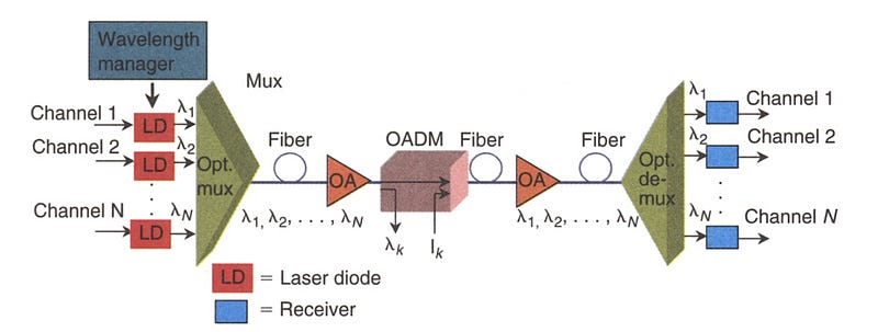
Point-to-point topology is typically found in long-haul transport, which demands for ultra high speed (10–40Gb/s), ultra high aggregate bandwidth, high signal integrity, great reliability, and fast path restoration capability. The transmitter and receiver within this DWDM topology can be several hundred kilometers away, and the number of amplifiers between the two end points is generally less than 10. Together with add-drop multiplexing, point-to-point DWDM topology enables the system to drop and add channels along its path. A DWDM point-to-point system includes lasers, an optical multiplexer and demultiplexer, fibers, optical amplifiers, and an optical add-drop multiplexer.
Ring-Configuration Mesh and Star Networks
Basically, a DWDM ring network includes a fiber in a ring configuration that fully interconnects nodes. Two fiber rings are even presented in some systems for network protection. This ring DWDM topology is commonly adopted in a local or a metropolitan area which can span a few tens of kilometers. Many wavelength channels and nodes may be involved in DWDM ring system. One of the nodes in the ring is a hub station where all wavelengths are sourced, terminated, and managed, connectivity with other networks takes place at this hub station. Each node and the hub have optical add-drop multiplexers (OADM) to drop off and add one or more designated wavelength channels. As the number of OADMs increases, signal loss occurs and optical amplifier is needed here.
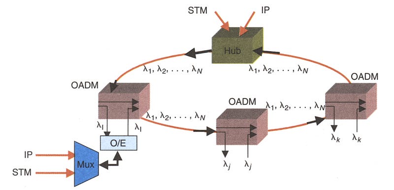
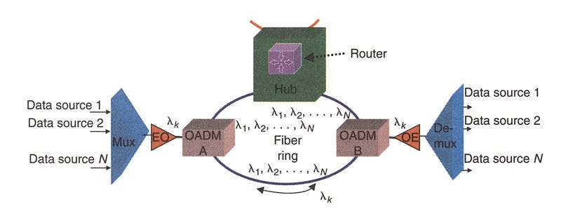
In the ring DWDM topology, a hub station works to manage channel assignment so that a fully connected network of nodes with OADM is accomplished. The hub also makes it possible to connect other networks. A DWDM mux/demux can be connected to an OADM node to multiplex several data sources. The following picture demonstrates a simple DWDM ring topology with a hub and two nodes (A and B).
Transmit and Receive Directions of DWDM Hub
In the previous part, we’ve mentioned DWDM hub, which serves as a very essential parts in a DWDM system. Here we further explain the transmit and receive direction of a DWDM hub, proving system solutions for your reference.
Transmit Direction
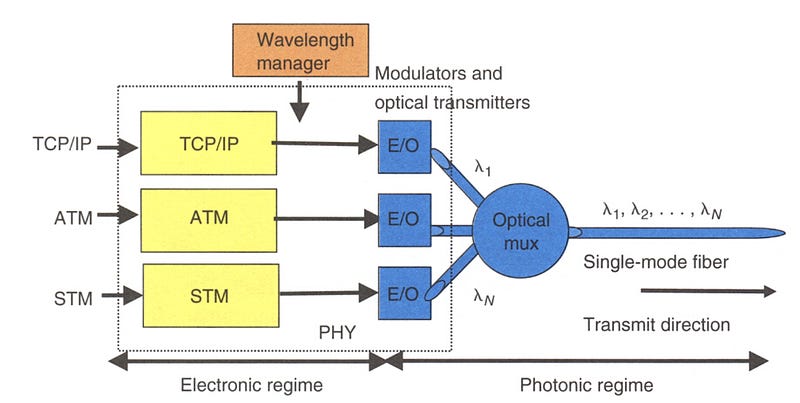
A DWDM hub accepts various electrical payloads, such as communications transport protoco/Internet Protocol (TCP/IP), asynchronous transfer mode (ATM), STM, and high-speed Ethernet (l Gb/s, 10 Gb/s). Each traffic type (channel) is sent to its corresponding physical interface, where a wavelength is assigned and is modulated at the electrical-to-optical converter. The optically modulated signals from each source are then optically multiplexed and launched into the fiber.
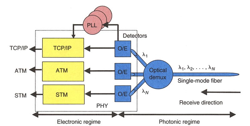
Receive Direction
When a hub receives a WDM signal, it optically demultiplexes it to its component wavelengths (channels) and converts each optically modulated signal to a digital electrical signal. Each digital signal then is routed to its corresponding electrical interface: TCPIIP, ATM, STM, and so on However, that each channel requires its own clock recovery circuitry because all channels may be at different bit rates.
Conclusion
The network topology of your DWDM system depends on various factors, including the number of nodes, maximum traffic capacity, scalability, number of fiber links between nodes and so on. Attentions also should be attached to the network components involved in the DWDM system. Hope this article could help to get more understanding towards DWDM technology.
If need more information about the DWDM/CWDM system, feel free contact Ivy from HTFuture: sales6@htfuture.com


没有评论:
发表评论