2019年4月27日星期六

The relationship and difference between OM1, OM2, OM3 and OM4

“OM” stand for optical multi-mode, which is a standard for multi-mode fiber representation of fiber grade. The bandwidth and maximum distance of different levels of transmission are different, and the differences between them are analyzed from the following aspects.

First. Comparison of parameters and specifications of OM1, OM2, OM3 and OM4 fibers

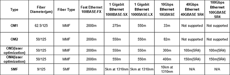
1. OM1 refers to a 50um or 62.5um core-diameter multimode fiber with a full injection bandwidth of 200/500MHz.km at 850/1300nm;

2. OM2 refers to a 50um or 62.5um core-diameter multimode fiber with a full injection bandwidth of 500/500MHz.km at 850/1300nm;

3. OM3 is a 850nm laser-optimized 50um core-diameter multimode fiber. In 10Gb/s Ethernet with 850nm VCSEL, the fiber transmission distance can reach 300m.

4. OM4 is an upgraded version of OM3 multimode fiber, and the fiber transmission distance can reach 550m.

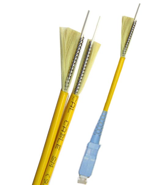
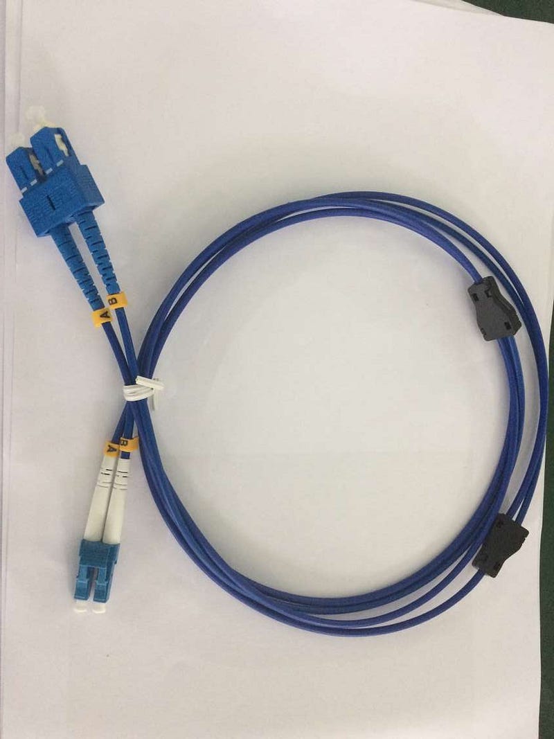
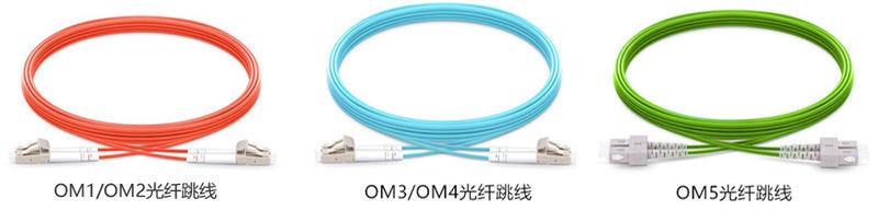
OM1 OM2 OM3 OM4 Cable

Second, the design comparison of OM1, OM2, OM3 and OM4 fiber

1. The traditional OM1 and OM2 multimode optical fibers are based on LED (Light Emitting Diode) as the basis light source, and OM3 and OM4 are optimized on the basis of OM2, making them suitable for light source. For the transmission of LD (Laser Diode laser diode);

2. Compared with OM1 and OM2, OM3 has higher transmission rate and bandwidth, so it is called optimized multimode fiber or 10G multimode fiber;

3. OM4 is re-optimized on the basis of OM3, with better performance.

Third, the function and characteristics of OM1, OM2, OM3 and OM4 fiber

1. OM1: large core diameter and numerical aperture, strong light collecting ability and bending resistance;

2, OM2: core diameter and numerical aperture are relatively small, effectively reducing the mode dispersion of multimode fiber, so that the bandwidth is significantly increased, the production cost is also reduced by 1/3;

3, OM3: the use of flame-retardant skin, can prevent the spread of flame, prevent the emission of smoke, acid gases and toxic gases, and meet the needs of 10 gb / s transmission rate;

4. OM4: Developed for VSCEL laser transmission, the effective bandwidth is more than double that of OM3.

Fourth, the application comparison of OM1, OM2, OM3 and OM4 fiber

1. OM1 and OM2 have been widely deployed in buildings for many years, supporting Ethernet transmission with a maximum of 1GB;
2, OM3 and OM4 fiber optic cable is usually used in the wiring environment of the data center, supporting the transmission of 10G or even 40/100G high-speed Ethernet road.

Fifth, When do you use OM3 fiber jumpers?

OM3 fiber is designed to work with VCSEL and meets the ISO/IEC11801–2nd OM-3 fiber specification to meet the needs of 10 Gigabit Ethernet applications. There are many types of OM3 fiber, including indoor type, indoor/outdoor versatility, etc. The number of cores of the fiber is from 4 cores to 48 cores. It also supports all applications based on older multimode 50/125 fiber, including support for LED sources and laser sources.

1. The transmission distance of Gigabit Ethernet using OM3 fiber system can be extended to 900 meters, which means that users do not have to use expensive laser devices when the distance between buildings is more than 550 meters.

2. Within the distance of 2000 meters, standard 62.5/125μm multimode fiber can be used in all cases within the OC-12 (622Mb/s) rate range, and single mode fiber will be used. However, the emergence of OM3 multimode fiber has changed this situation. Since OM3 fiber can increase the transmission distance of Gigabit and 10 Gigabit systems, the use of 850 nm wavelength optical module in conjunction with VCSEL will be the most cost-effective cabling solution.

3. When the link length exceeds 1000 meters, single-mode fiber is still the only choice. Single-mode fiber can achieve 5 km transmission distance at 1310 nm in Gigabit system, and 10 km in 10 Gigabit system. Transmission distance.

4. When the link length is less than or equal to 1000 meters, OM3 50μm multimode fiber can be used in the Gigabit system, and single mode fiber should be used in the 10G system.
5. When the link length is less than 300 meters, OM3 multimode fiber can be applied to any Gigabit and 10 Gigabit systems.

Sixth. When do you use OM4 fiber patch cords?

For a typical link, the cost of an optical module is about expensive. Although single-mode fiber is cheaper than multimode fiber, the use of single-mode fiber requires a very expensive 1300-nm optical module, which costs about 2–3 times that of a 850-nm multimode optical module. In general, a multimode fiber. The system cost is much lower than that of a single-mode fiber system.

When investing in fiber-optic cabling, if you can consider adding some initial investment in wiring, using better multimode fiber, such as OM4 fiber, you can ensure that the current multi-mode fiber technology is fully utilized to reduce the overall cost of the current system; When upgrading to higher speed systems, such as 40G and 100G, OM4 is still available and will be more cost effective.

In summary, when the transmission rate is greater than 1 Gb/s, the use of multimode fiber is a good system choice. When the system requires a higher transmission rate, the following are the guidelines for our choice of OM4 fiber:

1. For Ethernet users, the transmission distance can reach 300m to 600m in 10Gb/s system transmission; in 40Gb/s and 100Gb/s systems, the transmission distance is 100m to 125m.

2. For campus network users, OM4 fiber will support 4Gb/s fiber link length of 400m, 8Gb/s fiber link length of 200m or 16Gb/s fiber link length of 130m.

Conclusion

Multimode fiber technology has evolved from OM1 multimode to OM4, which now supports 10Gbps, which will give users the most effective return on investment and become the best choice for backbone cabling or fiber to the desktop.

If need OM1/OM2/OM3/OM4 cable, feel free contact Ivy from HTFuture: sales6@htfuture.com, HTFuture team are ready and happy to assist you.

2019年4月25日星期四

CWDM and DWDM for Metro Networks: How to Make it Economical?

Fiber exhaust still appears to be a common problem faced by most metro (or metropolitan) networks. Although the cost of fiber optic cable is consistently dropping, the trenching, labor, and other installation costs towards optical fiber stay rather high. This may partially explain why an increasing number of metro networks incline to adopt WDM technology to enhance fiber capacity. It is known that WDM technology used in metro networks generally takes two forms: coarse WDM (CWDM) and dense WDM (DWDM). This article will deliver an overall comparison of CWDM and DWDM in metro networks, from the perspective of the roles each plays and the operating cost. Help you to decide how to reach an economical solution.
CWDM vs. DWDM: Different Role in Metro Network
As for the major difference between the two WDM technology, their names imply it all: is the channel spacing within the window of the optical spectrum (see the picture below). CWDM has a wider pass-band that spaced at 20 nm apart, which allows for the use of less expensive components like uncooled lasers and thin-film filter technology. The cost advantage of CWDM makes it a more appropriate alternative for the shorter distance typically found in metro access networks.

However, metro networks sometimes demand for longer distance and more wavelengths that CWDM simply cannot satisfy, then DWDM with its narrow channel spacing (0.8 nm) should be put into use. The problem is that the components related to the latter are too expensive for some edge networks. In this case, the best solution is to combine both CWDM and DWDM in metro area networks.
CWDM in the Metro Access

CWDM nowadays commonly supports at least eight of the eighteen ITU-T G.694.2 defined channels over distances of up to 80 km. With simple point-to-point and ring network topology, CWDM eliminates the need for erbium doped-fiber amplifier (EDFA) typically associated with DWDM. CWDM’s lower cost and small footprint fit well with customer premises and co-location installations. And due to the readily available of Gigabit interface converters and small form factor pluggable (SFP) transceivers for CWDM platform, it gains in much popularity in enterprise and storage networks. CWDM is most fit in networks with the following features:
Low channel count of 4 to 8 channels
Transmission rates of <2.5 Gbits/sec per channel, and short distances of <80 km

DWDM in the Metro Core

Carriers are consistently looking for a cheaper and simpler version of long-haul DWDM, which drives the equipment suppliers to adapt DWDM systems accordingly. Banded wavelength filters, elimination of dispersion compensation, and more tolerant channel spacing were seen as ways to accomplish this goal. Nowadays, DWDM is well suited to high-capacity core networks in the metro, and to regional extensions between metro areas.

Cost Concerning CWDM and DWDM

The cost is still presented as a key difference in metro network systems. DWDM lasers are generally more expensive than those applied in CWDM system, the cooled DFB lasers offer cost-effective solutions for high-capacity large metro rings. And the cost of the this system is amortized over the large number of customers served by the systems. Whereas for metro access networks that demand for lower-cost and lower-capacity systems, it heavily depends on what the customer is willing to pay for broadband service. Since a metro access application would have fewer wavelengths, so based on equipment cost, CWDM is a more profitable solution for metro access points where cost is more important than capacity.

The Future of CWDM and DWDM in Metro Network

Some vendors offering both CWDM and DWDM technologies have merged the system building blocks onto a single platform. This approach allows the de-multiplexed CWDM traffic to be directly connected to DWDM transponders, saving equipment and space. It also enables end-to-end performance monitoring and cost optimization throughout the entire metro network. Then there is no need to choose between these two WDM technologies. The better choice is an integrated solution that makes use of the economies of CWDM for shorter distances, and provides the power of a DWDM network where longer distances and more capacity are needed. The result is an integrated, economical network that doesn’t require a carrier to compromise on quality, quantity, or cost. The DWDM building blocks are shown below.


Conclusion

From what we have discussed in this article, we can conclude that metro networks will benefit from the mixture of CWDM and DWDM systems. And metro networks are becoming more flexible over this converged solution: with CWDM fitting the needs of today, and DWDM for the growing demand for increased coverage in the future. Take advantage of both the coarse and dense WDM technology, this integrated metro network that delivers much reliability and flexibility is the trend of the future.

If need suggestions, feel free contact Ivy from HTFuture: sales6@htfuture.com, offers a variety of CWDM and DWDM equipment and we are ready and happy to assist you.

2019年4月22日星期一

CWDM vs DWDM, Which Option Is Best for You?

In the field of telecommunications, data center connectivity and video transport, fiber optic cabling are highly desirable. However, the reality is that the fiber optic cabling is no longer an economical or feasible choice to implement for each individual service. Thus using a Wavelength Division Multiplexing (WDM) for expanding the capacity of the fiber on the existing fiber infrastructure is highly advisable. WDM is a technology that multiplexes multiple optical signals onto a single fiber by using different wavelengths of laser light. A quick study of WDM fields will be put on CWDM and DWDM. They are based on the same concept of using multiple wavelengths of light on a single fiber. But they both have their merits and demerits. This article will take a look at the comparisons between CWDM vs DWDM to help you select the most suitable option for you.

CWDM vs DWDM: CWDM preferred for the following factors:

1. Low Cost

CWDM is much cheaper than DWDM because of hardware costs. CWDM system uses cooled lasers that is much cheaper than DWDM uncooled lasers. In addition, The price of DWDM transceivers is typically four or five times more expensive than that of their CWDM modules. Even the operating costs of DWDM is higher than CWDM. So CWDM is an ideal choice for those who have a limitation in funding.

2. Power Requirement

Compared with CWDM, the power requirements for DWDM are significantly higher. As DWDM lasers together with associated monitor and control circuitry consume around 4 W per wavelength. Meanwhile, an uncooled CWDM laser transmitter uses about 0.5 W of power. CWDM is a passive technology that uses no electrical power. It has positive financial implications for internet operators.

3. Easy Operation

CWDM systems use simpler technology with respect to DWDM. It uses LED or Laser for power. The wave filters of CWDM systems are smaller and cheaper. So they are easy to be installed and used.

CWDM vs DWDM: DWDM preferred for the below reasons:
1. Flexible Upgrade

DWDM is flexible and robust with respect to fiber types. DWDM upgrade to 16 channels is viable on both G.652 and G.652.C fibers. Originally from the fact that DWDM always employs the low loss region of the fiber. While 16 channel CWDM systems involve transmission in the 1300–1400nm region, where attenuation is remarkably higher.

2. Scalability

DWDM solutions allow the upgrade in steps of eight channels to a maximum of 40 channels. They allow a much higher total capacity on the fiber than a CWDM solution.

3. Long Transmission Distance

DWDM employs the 1550 wavelength band which can be amplified using conventional optical amplifiers (EDFA’s). It enhances transmission distance to hundreds of kilometers.
The following picture will give you a visual impression of the differences between CWDM and DWDM.

It is difficult to compare DWDM and CWDM against one another. The true difference is the number of channels needed by the customer and the cost associated with deploying each system. If need suggestions, feel free contact Ivy from HTFuture: sales6@htfuture.com, offers a variety of CWDM and DWDM equipment and we are ready and happy to assist you.

2019年4月21日星期日

DWDM Topology Design: How to Make it Right?

Network expansion spurs the demand for faster data transmission and higher capacity over the network. In this case, DWDM emerges as a cost-effective solution to handle these issues, working efficiently to combine multiple wavelengths together and sent them over one single fiber. With the ability to carry up to 140 channels theoretically, higher capacity can be achieved by DWDM technology. This article guides you through some basics of DWDM topology.

Common DWDM Topology Overview
DWDM networks are grouped into four major topological configurations: DWDM point-to-point with or without add-drop multiplexing network, fully connected mesh network, star network, and DWDM ring network with OADM nodes and a hub. The requirements of each DWDM topology differ, and based on various application, it may involve different optical components. Besides these four common DWDM topology, there also exists hybrid network topology, consisting of stars and/or rings that are interconnected with point-to-point links.

Configurations of DWDM Topology
This section illustrates the four basic DWDM topology configurations, help to understand the major differences and applications of them.

Point-To-Point Topology
Point-to-point topology is typically found in long-haul transport, which demands for ultra high speed (10–40Gb/s), ultra high aggregate bandwidth, high signal integrity, great reliability, and fast path restoration capability. The transmitter and receiver within this DWDM topology can be several hundred kilometers away, and the number of amplifiers between the two end points is generally less than 10. Together with add-drop multiplexing, point-to-point DWDM topology enables the system to drop and add channels along its path. A DWDM point-to-point system includes lasers, an optical multiplexer and demultiplexer, fibers, optical amplifiers, and an optical add-drop multiplexer.
Ring-Configuration Mesh and Star Networks
Basically, a DWDM ring network includes a fiber in a ring configuration that fully interconnects nodes. Two fiber rings are even presented in some systems for network protection. This ring DWDM topology is commonly adopted in a local or a metropolitan area which can span a few tens of kilometers. Many wavelength channels and nodes may be involved in DWDM ring system. One of the nodes in the ring is a hub station where all wavelengths are sourced, terminated, and managed, connectivity with other networks takes place at this hub station. Each node and the hub have optical add-drop multiplexers (OADM) to drop off and add one or more designated wavelength channels. As the number of OADMs increases, signal loss occurs and optical amplifier is needed here.
In the ring DWDM topology, a hub station works to manage channel assignment so that a fully connected network of nodes with OADM is accomplished. The hub also makes it possible to connect other networks. A DWDM mux/demux can be connected to an OADM node to multiplex several data sources. The following picture demonstrates a simple DWDM ring topology with a hub and two nodes (A and B).

Transmit and Receive Directions of DWDM Hub

In the previous part, we’ve mentioned DWDM hub, which serves as a very essential parts in a DWDM system. Here we further explain the transmit and receive direction of a DWDM hub, proving system solutions for your reference.

Transmit Direction

A DWDM hub accepts various electrical payloads, such as communications transport protoco/Internet Protocol (TCP/IP), asynchronous transfer mode (ATM), STM, and high-speed Ethernet (l Gb/s, 10 Gb/s). Each traffic type (channel) is sent to its corresponding physical interface, where a wavelength is assigned and is modulated at the electrical-to-optical converter. The optically modulated signals from each source are then optically multiplexed and launched into the fiber.
Receive Direction

When a hub receives a WDM signal, it optically demultiplexes it to its component wavelengths (channels) and converts each optically modulated signal to a digital electrical signal. Each digital signal then is routed to its corresponding electrical interface: TCPIIP, ATM, STM, and so on However, that each channel requires its own clock recovery circuitry because all channels may be at different bit rates.
Conclusion

The network topology of your DWDM system depends on various factors, including the number of nodes, maximum traffic capacity, scalability, number of fiber links between nodes and so on. Attentions also should be attached to the network components involved in the DWDM system. Hope this article could help to get more understanding towards DWDM technology.

If need more information about the DWDM/CWDM system, feel free contact Ivy from HTFuture: sales6@htfuture.com

2019年4月18日星期四

What is Armored Fiber Patch Cable?

With the development of telecommunication, demands for fiber patch cables are increasing all over the world. However, it is known to all that cables under harsh environment must be in need of better protection. Luckily, the advent of armored fiber patch cable efficiently solves the problem. As the name indicates, this type of optical cable is wrapped in a protective armor to prevent optical cables from animal bite, moisture, corrosion and other damage. Therefore, using armored fiber optic cable will greatly reduce the cost of unnecessary cable loss. This article will give you a basic introduction about the structure, types and advantages of armored optical cable.


Structure of Armored Fiber Optic Cable
Armored fiber optic cable has some basic layers. The first layer is the outer jacket made of plastic materials. It can protect the cable from the destroy of solvent and abrasion. The second layer under outer jacket is the strength member made of armored materials, such as aluminum foil, steel and kevlar. These materials are difficult to cut, bite and burn which are great protections for the optical cable. Next is the inner jacket of fiber made of protective and flame-retardant materials to support the internal optical fibers.
Types of Armored Fiber Optic CableArmored fiber optic cable can be divided into indoor armored optical cable and outdoor armored optical cable according to the premises.
Indoor Armored Optical Cable
This kind of optical cable includes double and single indoor armored fiber patch cables. The double armored cable has the stainless steel wire woven and stainless steel tube. On the contrary, the single armored cable does not contain the stainless steel components. Most of the indoor armored cables are deployed for building wiring applications. You may find them in walls, between floors, in plenum air handling ducts and under data center floors, etc.

Outdoor Armored Optical CableThere are light armored and heavy armored optical cable used for outdoor applications. The light armored cable has the protective plastic jacket with the same durability and longevity of a stainless steel cable, but its weight is much lighter. The heavy armored cable is wrapped in a wire circle which can be applied for riverbed and ocean floor.
Advantages of Armored Fiber Optic Cable
There are numerous advantages of armored fiber optic cable. The flexibility and durability of armored cable are excellent which makes it the right choice for industrial purposes. Moreover, the armor materials protect the cable from damage caused by animal, human or harsh environment, thus it can be applied to places where ordinary cables can not. The armored cable can also undergo heat and high pressure of extreme conditions. Using the armored optical cable not only ensures the high speed data transmission, but also extends the life span of cables.

ConclusionWhen fiber optic cables are needed for terrible conditions, a strong protection for the cable is very necessary. Therefore, to secure the data communication, armored fiber optic cable is a good solution to make the cable free from different damages. But when you operate the armored cables, you must be careful of the freshly cut edges which are very sharp to cope with. And the budget of your project should also be taken into consideration as armored cables are generally more expensive than the common ones.
If you need customized the Armored cables, for example: LC/UPC-LC/UPC, SM (2core 3mm type-A round duplex) LSZH armoured fiber patch cord, 20m or 300m or 2000m, free contact Ivy from HTFuture: sales6@htfuture.com , Ivy is ready and happy to assist you.

What compose the wavelength division multiplexing system? #WDM #DWDMSystem #CWDM #OTN #HTFuture

Wavelength Division Multiplexing (WDM) technology is a technology that simultaneously transmits multiple wavelength optical signals in a fiber optic fiber supplier. In order to make full use of the huge bandwidth resources brought by the low-loss area of ​​the single-mode fiber, the low-loss window of the fiber can be divided into several channels according to the frequency (or wavelength) of each channel, and the light wave is used as the carrier of the signal. The transmitter uses a WDM multiplexer supplier (synthesizer) to combine signal optical carriers of different specified wavelengths into one optical fiber for transmission.

The composition of the wavelength division multiplexing system

Optical Multiplexer (MUX): Multiple wavelengths are multiplexed into one fiber for transmission.
Optical Power Amplifier (OBA): compensates for the loss of the optical multiplexer and increases the fiber input power.
Optical Line Amplifier (OLA): compensates for fiber loss.
Optical Preamplifier (OPA): Improves the receive level and improves receiver sensitivity.
Optical Demultiplexer (DEMUX): Multiple wavelengths are split into individual fibers to separate the channels.
Optical Interface Converter (OTU): Converts the optical signal of a conventional SDH into a signal suitable for DWDM transmission.
Optical Monitoring Channel (OSC): A channel dedicated to the transmission of the monitoring system.


Wavelength division multiplexing

1 Make full use of the huge bandwidth resources of fiber
2 multiple types of signals can be transmitted simultaneously
3 System protection can maximize the protection of existing investments
4 High networking flexibility, economy and reliability
5 Reduce the ultra-high speed requirements of the device
6 compatible with all-optical switching

A WDM system can carry “service” signals in multiple formats, such as ATM, IP, etc.; in the network expansion and development, it is an ideal means of expansion, and is also the introduction of new broadband services (such as CATV, HDTV and B-ISDN, etc.) Advantageously, adding an additional wavelength can introduce any desired new service or new capacity; using WDM technology to achieve network switching and recovery, thereby enabling future transparent, highly survivable optical networks.


Wavelength division multiplexing classification

The design of the communication system is different, and the width of the interval between each wavelength is also different. According to the channel spacing, HTFuture WDM can be subdivided into CWDM (Sparse Wavelength Division Multiplexing) and DWDM (Dense Wavelength Division Multiplexing). The channel spacing of CWDM is 20nm, and the channel spacing of DWDM is from 0.2nm to 1.2nm, so CWDM is called sparse wavelength division multiplexing technology compared to DWDM.


If need more information about the DWDM/CWDM system, feel free contact Ivy: sales6@htfuture.com


2019年4月10日星期三

Which Is the Best 10G Network Solution: 10GBASE-T or SFP+?

The past few years have witnessed the extensive adoption of 10Gbps connectivity at data center equipment. The expansion 10 Gigabit Ethernet is supposed to satisfy the increasing demand for higher-performance servers, storage and interconnects. Since 10G network generally provides both optical and copper options, here comes the challenge for every IT technician: how to select the appropriate 10G connectivity solution? And could it be able to support data center deployments and trends concerning current situation and the future? In this article, we will compare 10GBASE-T and SFP+ options, and try to offer some help.
Options for 10G Network Connectivity
Two of the most widely used methods of connecting servers and storage to switches of 10Gb Ethernet network are using 10GBASE-T and SFP+. Many IT technicians are now evaluating the 10GBase-T technology, with the fact that 10GBase-T is easier to deploy and cheaper than the alternative SFP+ technologies.
10GBASE-T Option
The wide usage of 10GBASE-T being implemented takes the form of embedded RJ45 port. The advantage of which is that it allows users to capitalize on their existing Cat6a UTP structured cabling ecosystem. But the solution with embedded 10GBASE-T RJ45 ports lacks flexibility. And those unused ports still consume power thus resulting in higher operating cost.
SFP+ Option
For 10Gb/s data rates, SFP+ direct attach cables (DACs) are implemented as a fixed length of Twinax cable with SFP+ plugs integrated at both ends. Passive versions can be used for connections up to 7m and active versions for connectivity up to 15m. A DAC is a low power, low latency connection with flexibility. But it can be difficult to install through typical cable management. The difficulty increases with DAC length. Moreover, a DAC can be an expensive alternative as it does not take the advantage of the installed Cat6a structured cabling.
Comparison Between 10GBASE-T and SFP+
Comparing Power and Latency Advancements allow switch manufacturers to significantly lower power consumption on 10GBASE-T server and switch ports. A range of 10GBASE-T switches with 1.5 to 4 W per port are available on the market depending on distance.However, the SFP+ interface that has been widely deployed for 10 gigabit ToR switches continues to use less power, typically less than 1 W per port. It also offers better latency — typically about 0.3 microseconds per link. 10GBASE-T latency is about 2.6 microseconds per link due to more complex encoding schemes within the equipment.Features lower power consumption and lower latency, SFP+ is well suited for large high-speed supercomputing applications where latency is a critical factor and where high port counts can add up to significant power savings.
Comparing Cost and Interoperability
The cost of 10GBASE-T technology has been driven down in the past years. And with 10GBASE-T rapidly becoming the de factor LOM technology, the use of SFP+ means an additional cost of adapters for the servers. In comparing one of the latest SFP+ and 10GBASE-T ToR switches, the cost of 10GBASE-T ranges from 20% to 40% less.
10GBASE-T also has the advantage of being an interoperable, standards-based technology that uses the familiar RJ45 connector. It provides backwards compatibility with legacy networks. While SFP+ solutions are limited with little or no backwards compatibility.
10GBASE-T can offer more design flexibility using a structured cabling approach for longer distances up to 100 meters, as well as shorter ToR switch-server connections using category 6A patch cords. A structured cabling approach means that Category 6A cables can be field terminated on patch panels to any length for clean, slack-free cable management. However, SFP+ DAC offers less than 10m distance, and they are factory terminated and must be purchased in pre-determined lengths.
10GBase-T advantages
1.Lower deployment cost and easier to install and migrate
2.Much longer reach, 100 meter vs. 8.5 meter
3.Familiar RJ45 connectors and Cat 5/6/7 cables
4.Use of patch panels and structured wiring
5.Backward compatibility to 1 gigabit Ethernet or 100 megabit Ethernet
SFP+ DAC advantages:
1.Significantly lower overall cost, when you include switch, NIC and cable
2.Lower latency — 300 us per hop vs. 2.6 us per hop
3.Lower power and lower heat
4.Freely intermix fiber and DAC to meet distance requirements
HTFuture aim to be your Reliable Partner for different kinds of Compatible transceiver (QSFP28, QSFP+, SFP, XFP, SFP+ etc) | OTN optical transmission system|DWDM Mux Demux|OADM | OTU | EDFA | NMS | DCM | OLP | OBP etc| More information, welcome to contact Ivy: sales6@htfuture.com

2019年4月9日星期二

What factors we should consider when deploying 40G Ethernet?

When 10G network can not meet the increasing demand of the network, 40G network is more and more popular. With the continuous development, 40G Ethernet deployment has been accepted by more and more users. So do you know what factors should be considered when deploying 40G Ethernet? HTFuture will solve the doubts for everyone!

Compared with the deployment of 10G networks, 40G is a bit more complex and requires more consideration, following will analysis three main factors.
1. Selection of optical modules
In 40G networks, the main optical transceivers are QSFP and CFP modules, Since the demand for optical modules in the entire network deployment is very large, the cost of optical modules should not be underestimated.
However, the compatible module on the market has become more and more popular, and the performance is comparable to the original module, and the price is very reasonable. Therefore, when deploying 40G Ethernet, choosing the high-quality compatible module can not only ensure the efficiency, but also reduce the deployment cost greatly.
optical transceivers
2. Selection of cable
Now the optical cable is widely used, but copper cable still occupies an irreplaceable position. In the 40G network deployment, copper and fiber which is more suitable?
In wiring cost, copper price is low, deploying wiring costs are lower; For transmission distance, transmission distance of copper is only 7m. The optical fiber transmission distance is very long, for single-mode fiber is up to 10km, and the maximum transmission distance of multimode fiber is 100m to 150m.
3. 40G MPO components
Most of the 40G multi-mode optical modules are based on MPO technology that can increase the fiber density. According to the IEEE802.3ba standard, in general, the MPO connector is used for multimode fiber connections with standard lengths. But with the increase in the number of optical fiber, the data center wiring difficulty has increased accordingly. To solve this problem, most data centers choose pre terminated MPO components to deploy 40G networks. It greatly saves the cost and reduces the deployment difficulty, it is an effective solution. Therefore, it is critical to determine the length of the cable and the customized pre terminating MPO components before wiring.
Above are the factors that should be considered when deploying 40G ethernet. Nowadays, 40G is developing rapidly and gradually become the preferred solution for many enterprises. In the process of continuous development, 40G network deployment costs have also been reduced to some extent, which also makes 40G network deployment has been more widely used. HTFuture can provide you with an efficient and cost-effective solution to help you develop an economy and reliable 40G deployment plan. More information, welcome to contact Ivy: sales6@htfuture.com

2019年4月8日星期一

What is MPO Patch Cords? The types and application? #MPO #MPT

1. What is the MPO patch cord ?
MPO connector is the short of Multi-fiber Push On, it is one of the MT connector series,
This connector has more than 1pcs ferrule, snapped into place by mechanical means.
MTP connector is a multi-innovative and high-performance MPO connector, that is optically and mechanically superior to typical MPO connectors.
MPO connectors and fiber optic cable can be processed to produce various forms of MPO patch cords.
2. What are the types of MPO patch cord?
For the MPO patch cords, there are many types:
a. Core: 8core / 12core / 24core / 36core / 48core / 72core / 144core;
b. Have branch or not: MTP / MPO trunk patch cord and MTP / MPO branch patch cord, branch have the connector of SC/LC/ST/FC;

c. PIN connecting Type: Direct connection Type A / Cross Type B / Pair Cross Type C / Universal Config Type D: 

d. Female & male: Female to Female / Male to male / Female to male;
e. Patch cord type: Multi-mode / Single-Mode.
f. Distance: different distance patch cords as you want.
3.What is the application of the MPO patch cord?
The MTP / MPO series is a group of highly innovative products that have brought optical transmission to a new era.
It is widely used in the data center SAN / Enterprise Network / Campus Network...
4.What are the MPO patch cord HTFuture can supply?
HTFuture can supply the MPO patch cord as the upper said. Any problems, welcome to contact our sales Ivy: sales6@htfuture.com

2019年4月3日星期三

What people will do on Qingming Festival (also called Tomb Sweeping day)?

Qingming Custom:

Qingming is an important traditional Chinese festival also known as Tomb-Sweeping Day. This festival reminds us the importance of the family members in our lives which is one of the beauty of Chinese culture.

During Qingming, Chinese families visit the tombs of their ancestors to clean the gravesites, pray to their ancestors, and make ritual offerings. 

The holiday recognizes the traditional reverence of one's ancestors in Chinese culture. 

Now chinese people is changing, Vigorously promote the "flower sacrifice sweep", "planting tree sacrifice sweep", "online sacrifice sweep", "community public sacrifice", "collective public sacrifice" and "family memorial service" and other healthy and civilized ways, expressing sympathy and admiration for the ancestors, reducing the environment for the mountains Pollution and fire hazards, maintaining a good ecological environment for green mountains and green hills.


China's fifth solar term, Clear and Bright, will begin on April 5, which coincides with a traditional Chinese festival, Qingming Festival, or Tomb-Sweeping Day.

The festival also marks a change in the weather, as temperatures begin to rise nationwide and rainfall increases, making it a crucial time for plowing and sowing in the spring.


《清明》 

 (唐)杜牧 

 清明时节雨纷纷,路上行人欲断魂。 

 借问酒家何处有?牧童遥指杏花村。 

 ( 杨宪益、戴乃迭英译《清明》((无韵译法) (古诗苑汉英译丛《唐诗》,外文出版社,2001) ) 

 It drizzles endless during the rainy season in spring, 

 Travelers along the road look gloomy and miserable。 

 When I ask a shepherd boy where I can find a tavern, 

 He points at a distant hamlet nestling amidst apricot blossoms。 


Dear All Customer,

Please kindly note that we will have Tomb Sweeping Festival Holiday from April 5th to 7th.

We will back to work on 8th April, 2019. Any urgent things on optical transceiver order, OTN optical Transmission, Protection and Monitoring solution, can contact us by email. Our sales team will reply you ASAP.

Contact Ivy: sales6@htfuture.com

Best regards,

HTFuture team


Single Fiber Qsfp28 80km Lc Optical Module

  Now only one fiber can transmit 100G under distance 80km. 100G BIDI 80km. why use this optical module? (1) save one fiber rent. (2) easy t...