2025年6月12日星期四

Which thing need consider when deploy 400G between data center distance in 120KM?

 In an era characterized by explosive data growth and the relentless expansion of cloud computing services, the demand for high - speed and long - distance data transmission between data centers has reached unprecedented levels.

For 100M distance, can use the following solution. But for Longer distance, HTF also has the solution.

Article content

400G optical transmission technology represents a significant leap forward in data communication. It offers extremely high bandwidth, enabling the transfer of vast amounts of data in a short time. For data centers, which serve as the core hubs of data storage and processing, 400G can meet the increasing requirements for data exchange between different centers, such as real - time data synchronization, large - scale data migration, and cloud service interoperability. The higher data rate not only improves the efficiency of data center operations but also provides a solid foundation for emerging technologies like artificial intelligence and big data analytics, which rely on rapid data transfer.

However, when considering a 120 - kilometer distance between data centers, several challenges need to be addressed. One of the primary obstacles is optical signal attenuation. As light travels through optical fibers, its power gradually decreases due to factors such as absorption and scattering within the fiber material. Over a 120 - kilometer span, the attenuation can be substantial, potentially degrading the signal quality to a point where data errors occur frequently.

Another critical issue is chromatic dispersion. Different wavelengths of light in an optical signal travel at slightly different speeds in the fiber, causing the signal to spread out over time. In long - distance transmission, chromatic dispersion can lead to inter - symbol interference, which severely impacts the integrity of the transmitted data.

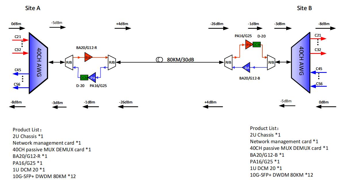
Despite these challenges, there are several technological solutions that can make 400G deployment over 120 kilometers a reality. Advanced optical amplifiers, such as erbium - doped fiber amplifiers (EDFAs) and Raman amplifiers, can be strategically placed along the fiber route to compensate for signal attenuation. EDFAs boost the optical signal power by amplifying the light within the fiber using the gain medium of erbium - doped fiber, while Raman amplifiers utilize the Raman scattering effect in the fiber to amplify the signal over a wide bandwidth.

To deal with chromatic dispersion, dispersion , HTF use coherent optical module to solve the this chromatic dispersion issue. Use coherent optical module, so don't need consider the DCM. Less optical parts.

In addition, modulation formats and coding techniques also play crucial roles. Advanced modulation formats like quadrature amplitude modulation (QAM) can increase the spectral efficiency of the 400G signal, allowing it to carry more data per unit bandwidth while maintaining a certain level of tolerance to signal degradation. Forward - error - correction (FEC) coding can detect and correct errors that occur during transmission, improving the reliability of the data link. By combining these technologies, it is possible to achieve stable 400G transmission over 120 kilometers.


Article content


Article content

HTF can hel pyou deploy 400G between data centers separated by 120 kilometers, Max support 40x400G, If need upgrade your data center network, welcome to contact HTF. ivy@htfuture.com

Article content

2025年5月20日星期二

16T DWDM solution with OLP

 First open 1x400G, future max can expand to 40x400G=16000G.  Help you save fiber rent and cost. 

OLP offers high reliability with automatic failover, dual-path protection, 
transparency, easy deployment, cost-effectiveness, and wide applicability for optical networks.

Point-to-point transmission, Dual fiber
Single channel transmission: 400G
Primary line distance: 80km 
Secondary line distance : 100km
Span attenuation: 0.3dBm/km


2025年5月11日星期日

DWDM Application scenarios of 400G technology

 400G wavelength division technology is a bearer technology for the next decade. The total bandwidth of the 80*400G system reaches 32T. Considering the current traffic growth, network construction cost, and technology evolution, priority is given to the construction of 400GE port supporting networks in the backbone 163 hotspot areas and some metropolitan IP services, as well as the large bandwidth bearer scenarios for government and enterprise customers of East Data West Computing, multi-AZ connections between clouds, and intelligent computing:

Backbone communication network: From the current analysis of the growth of backbone 163 traffic and flow direction, the traffic between the major economic circles of Beijing-Tianjin-Hebei, Yangtze River Delta, Guangdong, Hong Kong and Macao, and Chengdu-Chongqing is relatively large, and the long-distance 400G QPSK technology can meet the construction of regional ROADM networks. Other areas of the backbone network can continue to use the original 100G ROADM network for traffic carrying. For some provincial trunks, PCS-16QAM technology can be considered, with a capacity of up to 48T and a lower cost than QPSK long-distance technology.

Metro communication network: Around the East Data West Computing hub node, the bandwidth growth in the provincial trunk and metropolitan area is expected. According to the expected traffic growth, 400G networks can be built in some provincial trunk hub nodes, East Data West Computing nodes, and metropolitan core nodes to meet the demand for bandwidth growth.

Cloud-to-cloud large bandwidth network: For highly reliable multi-AZ cloud-to-cloud and cloud-to-intelligence interconnection scenarios, the current 100G network has a total bandwidth of 8T, which cannot meet its business needs. Considering the occupied computer room, power consumption, operation and maintenance, and single bit cost, it is better to introduce 400G or higher speed to solve the requirements of large-scale data processing and storage for high-speed interconnection.

Four future development trends

The popularity of ChatGPT has promoted the construction of domestic intelligent computing centers. With the implementation of intelligent computing centers, intelligent computing applications will be launched quickly, and AI-generated videos will become easier and easier, further generating new traffic and promoting network connections. With the expansion of the application scale of 400G, the maturity of the industrial chain will further promote technological innovation and reduce manufacturing costs. In addition, with the development of silicon photonics technology, the future 400G wavelength division system will be more efficient, energy-saving, and less expensive.

If you want to build 400G dwdm transmission network, welcome to contact Ivy from HTF. ivy@htfuture.com

2024年5月24日星期五

Single Fiber Qsfp28 80km Lc Optical Module

 Now only one fiber can transmit 100G under distance 80km.


100G BIDI 80km.

why use this optical module?

(1) save one fiber rent.

(2) easy to use and connect to Huawei/Cisco/Juniper switch directly.

(3) If two fibers can expand capacity to 200G.

don't need to add dwdm equipment.

(4) under 80km and small fiber loss environment.

can transit directly.

(5) Save engineer's time for upgrading 10G to 100G network easily and quickly.

Suitable for data center internet connect.

If want more details, welcome to contact Ivy from HTF.
ivy@htfuture.com    +8618123672396


2024年4月22日星期一

Why need Single Fiber DWDM Applications?

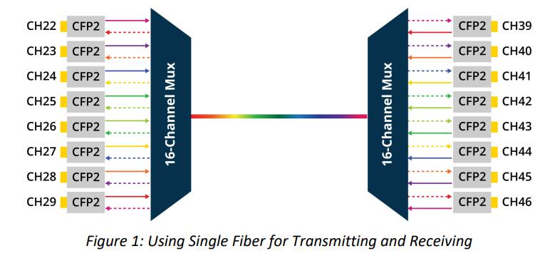
 Fiber optic networking used to require two fibers, one for transmitting and one forreceiving signals simultaneously. Single fiber solutions emerged as a way to reduce costs ofdark fiber solutions and optimize fiber. Rather than using two dedicated strands, a single fiber strand that carries a bi-directional signal is used.


For enterprises leasing dark fiber from providers, the operational savings are significant. The challenge is to maximize revenues while reducing their largest expenditure - monthly cost of the fiber link. Using single fiber reduces operational costs by 50%, making dark fiber an affordable solution. 

In DWDM, active and passive solutions for single fiber transmission range from 4 up to 8 400G wavelengths, with optional optical amplifiers. The single fiber solution seamlessly
integrates with any standards-based 10/25/100Gb Ethernet, 16/32G Fibre Channel, and OTU2/2e/4 client interfaces, and supports any mix of up to 400G services. 

Single fiber solutions are recommended for the following applications:
• Point-to-point, ring or linear add and drop topologies, where installing new fiber is difficult or expensive
• Enables splitting enterprise traffic over two different fibers as opposed to using the same fiber for the entire traffic
• Increase reliability to an existing dual fiber solution by using one fiber for transmitting and receiving, and one for protecting.

The single fiber solution is more efficient and economical for many applications and needs, and provides the same performance and throughput as the traditional dual fiber solution. It enables customers to utilize single fiber for both transmitting and receiving, significantly maximizing their investment and reducing costs such as monthly leasing, taxes, or laying additional fibers.

The solution is transparent to the client optical interface and suits 400G, 100G, 10G, and sub-10G with any client interface mix. It incorporates a single mux with 8 or 16 channels. Half of the mux is used for transmitting and half for receiving.


If you need single fiber soluiton, welcome to contact HTF team, HTF will help you design the suitable DWDM solution. Support single fiber or dual fiber.

www.htfuture.com   ivy@htfuture.com   +8618123672396

2024年4月17日星期三

Where DWDM use?

DWDM is often used by telecommunications, cable and data centers as part of their optical transport network.


Carrier Transport Network

The carrier transport network is made up of several layers of aggregation called the access network, metro aggregation network, edge network and the core backbone network. DWDM is most often used in the metro aggregation network and the core backbone network.


DWDM in the metro aggregation network is used to combine data from several cities. As service providers bring more computing capabilities closer to their customers, DWDM is also flexible enough to meet their needs for higher bandwidth aggregation as they begin to converge more data into a single node to compute. The core backbone often deals with the high-speed switching of large amounts of data between their major central offices, which can span across several regions, states or even countries, which is also ideal for using DWDM.

If need more information, welcome to contact HTF. www.htfuture.com

2024年4月16日星期二

What is BA, LA, PA in the DWDM System?

 Erbium doped fiber amplifiers (EDFA) are now the most preferred and widely used optical amplifier for long-haul fiber-optic communications.

Booster amplifier (BA), in-line amplifier (LA), and pre-amplifier (PA) are the three types of EDFAs used in DWDM optical transmissions. They are typically deployed in combinations and placed at different locations along the transmission line to ensure that the signal is transmitted to the receiver.

The booster amplifier works at the transmission side of the link, which is used to amplify the optical signal before it launches into the fiber link. It is characterized by high input power, high output power and medium optical gain.


The in-line amplifier operates in the middle of the optical link, which is designed for optical amplification between two network nodes. It features low to medium input power, high output power, high optical gain, and low noise figure.


The pre-amplifier is placed at the receiving end of the optical link and is used to compensate for the losses of the demultiplexer near the optical receiver. It is characterized by medium to low input power, medium output power, and medium Gain.

2024年4月10日星期三

What is OLP?

 What is OLP?

#OLP #DWDM #Datacenter #Protection #HTF
For example, you want to transmission 100G from Site A to site B.
There are 2 routings, you only choose routing 1, If the optical cable is broken, the transmission is interrupted.

You choose 2 routings, add OLP,  Routing 1 is primary link , and routing 2 is secondary link, If the optical cable is broken, the transmission will automatically jump from the primary link to the secondary link. Ensure uninterrupted business

Add OLP, need double routing. If you don't have redundent routing, suggestion not add OLP.


2024年3月28日星期四

Optical Transceiver 1310nm fail to transmiss on G.655 optical fiber

 Have you ever encountered the problem that the link cannot be up when the 1310nm optical module is transmitted on G.655 optical fiber? I encountered this kind of problem recently, and now I want to share it with you.


Failure symptom

Module: 100G QSFP28 1310nm 80km optical transceiver

Switch: Cisco NCS540

Optical fiber type:  G.655, distance 50km

Failure symptom:  Transmission link cannot go up.

Analysis:

1.Change another switch, the link continues flap

2.Use G.652 optical fiber test in lab, Link works ok. Optical module Tx power and Rx power are in spec. That means optical transceivers performance are ok.

3.DWDM optical modules work well on G.655 link,that means G.655 link no break.   

4.Deduce:The optical module wavelength and fiber type don’t match

Root Cause:

Optical modules with a working wavelength of 1310nm cannot use G.655 optical fiber for long-distance transmission, G.655 Optical cable cutoff wavelength ≤ 1480nm, work window is C band and L band (1530nm~1625nm) , which means if wavelength smaller than 1480nm,cannot use on  G.655 

Summary:

1. G.655 optical fiber cannot transmit 1310 nm signals because the cut-off wavelength of G.655 optical fiber is 1480 nm.

2. If the input power and receive power are normal but the link cannot be up, it is usually because the optical module type does not match the fiber type.

2024年3月26日星期二

What are the speed and modulation formats used by 800G OSFP/QSFP-DD modules?

all 800G modules make use of 8x electrical lanes in both directions, comprising 8 transmit lanes and 8 receive lanes. Each lane operates at a data rate of 100G PAM4, resulting in a total module bandwidth of 800Gb/s. Additionally, the optical output of all 800G transceivers comprises 8 optical waves, with each wave modulated at 100G PAM4 per lane.


If want to know more and buy this product, welcome to contact Ivy from HTF, ivy&htfuture.com

HTF can help you expand the network capacity by DWDM solution.  


HTF can help you design coherent 400G/200G/100G DWDM/OTN solution, DWDM Single lamda support 100G/200G/400G Dual fiber/Single fiber Ultra long distance transmission. Expand your network capacity and DCI network easily.

Can OSFPs be plugged into a QSFP-DD port, or QSFP-DD’s plugged into an OSFP port?

 No. The OSFP and the QSFP-DD are two physically distinct form factors. For OSFP systems, OSFP optics and cables must be used, and for QSFP-DD systems, QSFP-DD optics and cables must be used.


If want to know more and buy this product, welcome to contact Ivy from HTF, ivy&htfuture.com

HTF can help you expand the network capacity by DWDM solution.  


HTF can help you design coherent 400G/200G/100G DWDM/OTN solution, DWDM Single lamda support 100G/200G/400G Dual fiber/Single fiber Ultra long distance transmission. Expand your network capacity and DCI network easily.

2024年3月24日星期日

What a Linear Drive Module is?


Amidst the high-speed optical module landscape, the incorporation of DSP chips for signal processing has been the norm. These chips, featuring ADC/DAC, FEC, retiming, reshaping, adaptive equalization, and more, hold immense power, yet their potency comes at the cost of significant power consumption and expenses. A typical 7nm DSP in a 400G optical module consumes around 4W, constituting 50% of the module’s power consumption.

DSP Function Block Diagram

The following figure shows the power consumption breakdown of a 400G ZR optical module, with a similar scenario for an IMDD.

As a response to the need for efficiency, the revolutionary concept of Linear-drive technology emerged.

How can the power consumption and cost impact caused by DSP be mitigated?

By forgoing DSP within the optical module and integrating its functions into switching chips, a streamlined design emerges. The result? A compact configuration housing only driver and TIA components. Diverging from the traditional driver and TIA functions, those in the Linear Photonic Optics (LPO) architecture include CTLE and Equalization features, facilitating signal compensation. Notably, the Linear Drive concept obviates the need for retiming, eliminating non-linear processes and thus dubbed the Non-retimed module.

LPO’s merits encompass several facets:

  • Low Power Consumption: LPO yields a 50% reduction in power consumption compared to pluggable optical modules, aligning closely with CPO power levels.

The overall power consumption of the switch system will be reduced by about 25 percent, as below.

  • Low Latency: Omitting DSP significantly reduces system latency, ideal for latency-sensitive scenarios like inter-GPU communication within High-Performance Computing (HPC) centers.
  • Cost Efficiency: The absence of 5nm/7nm DSP chips translates to cost savings. In an 800G module, the Bill of Materials (BOM) cost totals around $600-$700, with DSP chips accounting for approximately $50-$70. While EQ integration within Driver and TIA adds $3-$5, the total system cost reduction amounts to around 8%.
  • Hot-Pluggability: LPO retains the convenience and reliability of pluggable modules, leveraging established optical module supply chains. This distinguishes LPO from CPO, which is still less widely adopted due to reliability and cost considerations.
Comparison of various dimensions of conventional optical modules, LPOs and CPOs

In summary, LPO represents a novel approach with its unique advantages and ongoing challenges.

  1. Integration of DSP Chips: To implement LPO, there’s a need to integrate DSP chips into switches, which requires the involvement of switch chip manufacturers. The LPO concept has also stirred the competition among DSP chip manufacturers, such as Broadcom and Inphi.
  2. New Protocols and Testing Methods: Introducing LPO necessitates the development of new protocols and testing methods. The Optical Internetworking Forum (OIF) is currently working on defining the CEI-112G-LINEAR standard to address this need.
  3. Applicability and Distance: One concern is whether LPO is suitable for longer distances, potentially reaching kilometers. As DSP chips are no longer present in the module, there may be a decrease in error performance, leading to a reduction in transmission distance.

While several companies showcased their linear-drive solutions, particularly during OFC 2023, and launched LPO options post-event, the transition from technical discussions to widespread adoption is ongoing. The introduction of LPO underscores the industry’s pursuit of low-power, low-cost, high-speed optical modules.

Which thing need consider when deploy 400G between data center distance in 120KM?

  In an era characterized by explosive data growth and the relentless expansion of cloud computing services, the demand for high - speed and...