As an integral part of the entire network, optical transceiver plays a significant role in deciding the overall performance and reliability of the network. The importance of optical transceiver testing therefore cannot be overestimated. Currently, since an increasing number of optical transceivers employed in networks is provided by third party suppliers, to ensure their compatibility and interoperability becomes more of a concern than ever. Well, this article is here to help you deliver effective optical transceiver testing.
Optical Transceiver Overview
Generally, an optical transceiver consists of a transmitter and a receiver. When a transmitter is connected with a receiver but the system doesn’t achieve your desired bit-error-ratio (BER), is there something wrong with the transmitter or the receiver? The transmitter and the receiver can affect each other, thus, specifications should guarantee that any receiver will interoperate with a worst-case transmitter, and any transmitter will provide a signal with sufficient quality such that it will interoperate with a worst-case receiver.
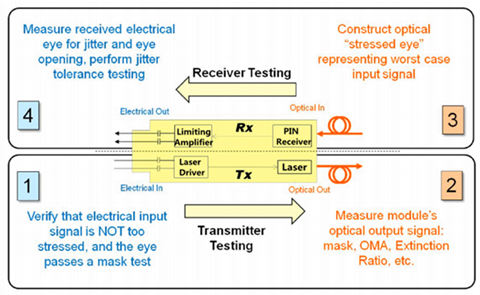
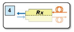
Precisely, defining worst case is often a complicated task. If a receiver needs a minimum level of power to achieve the system BER target, then that level will dictate the minimum allowed output power of the transmitter. If the receiver can only tolerate a certain level of jitter, this will be used to define the maximum acceptable jitter from the transmitter. In general, there are four basic steps for optical transceiver testing, as shown in the following picture, which mainly includes the transmitter testing and receiver testing.
Transmitter Testing
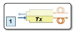
Transmitter parameters may include wavelength and shape of the output waveform while the receiver may specify tolerance to jitter and bandwidth. As an vital part in transceiver testing, testing a transmitter usually consists of two steps:
1. The input signal used to test the transmitter must be good enough. Measurements of jitter and an eye mask test must be performed to confirm the quality using electrical measurements.
An eye mask test is a common method to view the transmitter waveform and provides a wealth of information about overall transmitter performance.
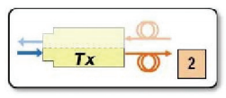
2. The optical output of the transmitter must be tested using several optical quality metrics such as a mask test, OMA (optical modulation amplitude), and Extinction Ratio.
Receiver Testing
Testing the receiver also serves as an essential part in transceiver testing. similarly, there are two steps:
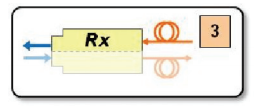
1. Unlike testing the transmitter, in which case one must ensure that the input signal is of good quality, testing the receiver involves sending in a signal of poor enough quality. In this case, a stressed eye represents the worst case signal shall be created. This is an optical signal, and must be calibrated using jitter and optical power measurements.
2. The last step is to test the electrical output of the receiver. There are three basic categories we should follow:
- A mask test, which ensures a wide enough eye opening. The mask test is usually accompanied by a BER (bit error ratio) depth.
- Jitter budget test, which tests for the amount of certain types of jitter.
- Jitter tracking and tolerance, which tests the ability of the internal clock recovery circuit to track jitter within its loop bandwidth.
Conclusion
Complicated as it is, fiber optic transceiver testing is also an indispensable step to ensure overall network performance. As basic eye-mask test offers an effective and commonly used option for transmitter testing, testing the receiver can be more complex and requires more testing methods. A wide variety of fiber optic transceivers are available in Htfuture that are compatible with major brands on the market, such as Cisco, HP, IBM, Juniper, etc. Moreover, each fiber optic transceiver has been tested with the original-brand switch to ensure its high performance and superior quality. For more detailed information, please visit www.htfuture.com
HTFuture aim to be your Reliable Partner for different kinds of Compatible transceiver (QSFP28, QSFP+, SFP, XFP, SFP+ etc) | OTN optical transmission system|DWDM Mux Demux|OADM | OTU | EDFA | NMS | DCM | OLP | OBP etc| More information, welcome to contact Ivy, contact Ivy. Email: sales6@htfuture.com Skype: live:sales6_1683
HTFuture team are ready and happy to assist you.


没有评论:
发表评论