2019年6月25日星期二

Things You Need to Know about Fiber MUX and DEMUX

With the development of the network, fiber MUX and DEMUX arouse many people’s interest in the telecommunication field. This passage will focus on the three questions. What are they? 

How do they work? When to choose which?

What Are Fiber MUX and DEMUX?

A multiplexer (or mux) is a device that selects one of several analogs or digital input signals. And then it forwards the selected input into a single line. Conversely, the data distributor is demultiplexer. demux for short. It is the exact opposite of the multiplexer. Fiber MUX is a device taking a single input signal and selecting one of many data-output-lines, which is connected to the single input.

How Do They Work?

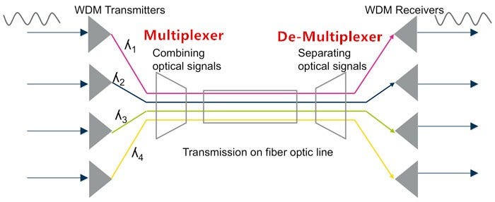
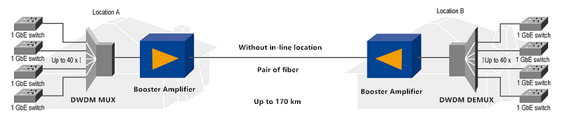
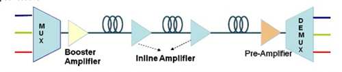
As you know, a multiplexer is often used with a complementary demultiplexer on the receiving end.
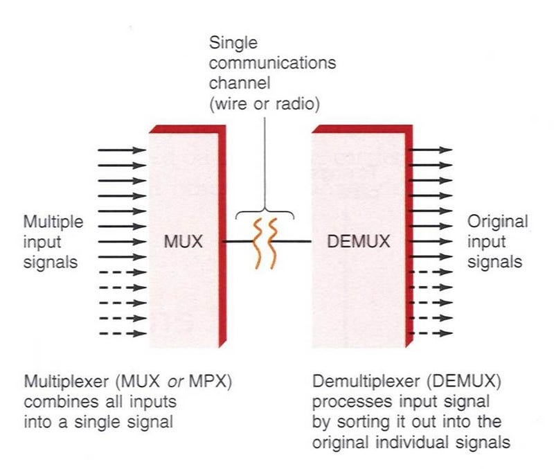
The picture shows that the circuit consists of a multiplexer (MUX) at the transmitting side and a demultiplexer (DEMUX) at the receiving side. A multiplexer is a switch that routes the input to one of its many outputs. the outputs are chosen depending on the binary number at its ‘select’ lines. The DEMUX works in a reverse manner to the MUX.

Mux

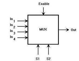
A multiplexer, also called data selector, is a combinational logic circuit. It selects one of the 2n inputs on the end route to the output. A multiplexer of 2n inputs has n select lines. They are used to select which input line to send to the output. Multiplexers are mainly used to increase the amount of data over the network within a certain amount of time and bandwidth. The following picture shows how does a MUX work.
DEMUX

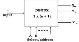
The demultiplexer is a combinational logic circuit. It performs the reverse operation of the multiplexer. DEMUX has only one input, n selectors and 2n outputs. Depending on the combination of the select lines, one of the outputs will be selected to take the state of the input. The demultiplexer converts serial data signals at the input to a parallel data at its output line. The process is shown in the picture.

When to Choose Which?

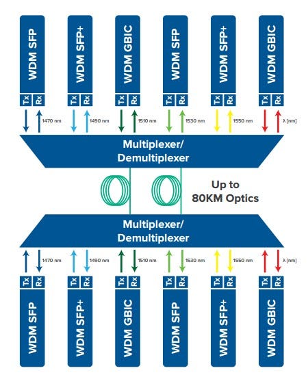
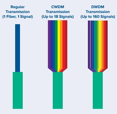
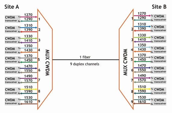
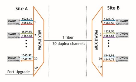
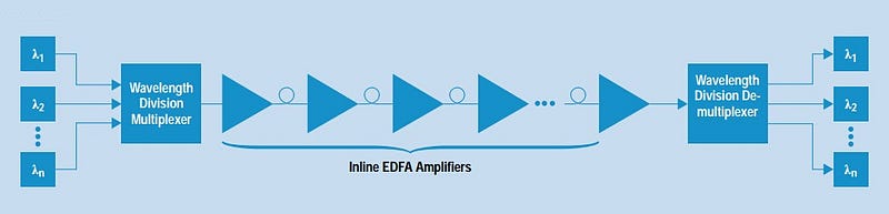
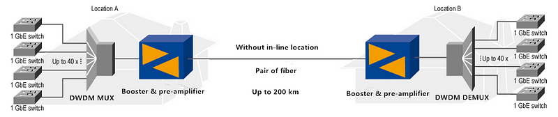
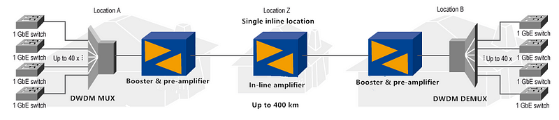
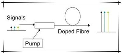
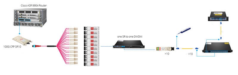
According to the working principles, MUX and DEMUX can be used in several situations. For example, communication system, computer memory, the telephone network, etc. MUX and DEMUX play a vital role in CWDM and DWDM system. In the WDM system, MUX combines multiple signals onto one single line. While demultiplexer separates the single data stream out to original signals. MUX and DEMUX in WDM are cost-saving. They are used by connecting a multiplexer and a demultiplexer together over a single channel.

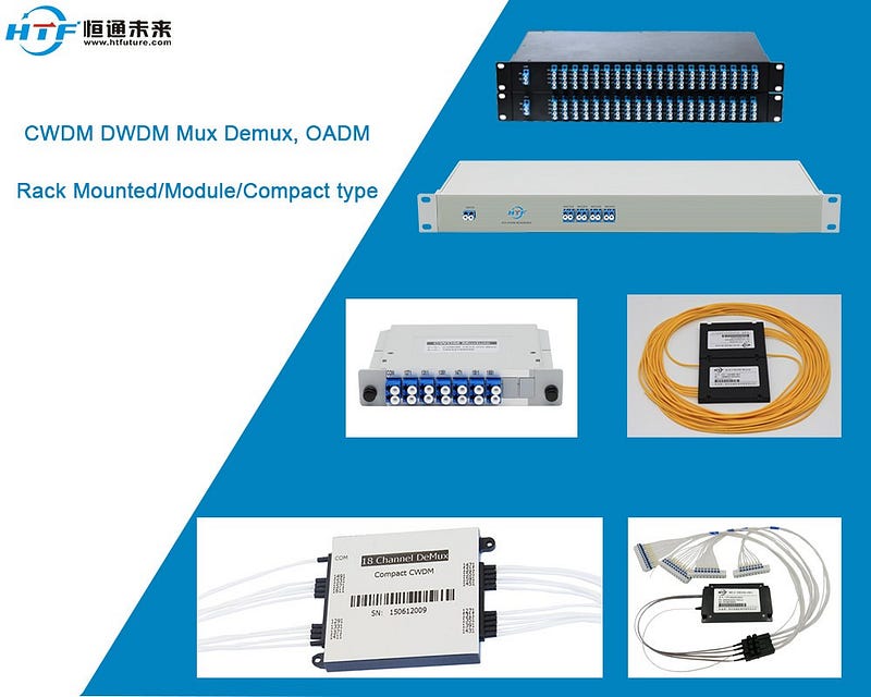
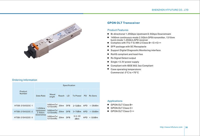
After reading this passage, you may have got the basic knowledge of fiber MUX and DEMUX. HTFuture, a leading WDM modules suppliers, offers a series of WDM modules. Such as 40 channel DWDM Mux, 4 channel mux-demux, CWDM 8 channel Mux Demux, 8 channel fiber Mux DWDM, CWDM passive Demux, and other network switches. You can know more details of our excellent WDM MUX/DEMUX at www.htfuture.com

Ivy: sales6@htfuture.com Skype: live:sales6_1683
HTFuture team are ready and happy to assist you.

2019年6月19日星期三

How to Use WDM for Fiber Capacity Expansion?

Imagine turning a cottage into a majestic skyscraper without having to deliver any innovation or construction. This is what wavelength division multiplexing (WDM) allows with your existing fiber optic network. The hunger for bandwidth propels service providers to make a substantial investment in upgrading fiber cabling infrastructure. This can be a challenge both economically and practically. However, the WDM technology offers an alternative to increase capacity on the fiber links that are already in place. Without deploying additional optical fiber, WDM greatly reduces the cost of network expansion.

WDM Technology Explanation

Let’s begin with the most fundamental question: What is WDM technology? Short for wavelength division multiplexing, WDM is a way of transmitting multiple simultaneous data streams over the same fiber. Since this happens simultaneously, WDM does not impact transmission speed, latency or bandwidth. WDM functions as multiplexing multiple optical signals on a single fiber by using different wavelengths, or colors, of laser light to carry different signals. Network managers can thus realize a multiplication effect in their available fiber’s capacity with WDM.
To implement WDM to the infrastructure is rather simple, WDM setup generally consists of the following:
  • WDM transmit devices, each operating at a different wavelength
  • Multiplexer, a passive device that combines the different light sources into a blended one
  • Fiber infrastructure
  • De- Multiplexer, a passive device that splits the blended light source into separate ones
  • WDM receive devices
What Capacity Increase Can We Expect?

There are two variants of WDM: CWDM (coarse wave-division multiplexing) and DWDM (dense wave-division multiplexing). The only difference between them is the band in which they operate, and the spacing of the wavelengths and thus the number of wavelength or channels that can be used.

When using WDM on existing fiber cabling, you should also consider the fiber type (single-mode or multimode) and loss level. For CWDM, 8 to 18 devices may be possible, whereas for DWDM, up to 40 channels are the most common case, but it is possible to reach up to 160 channels.
Choose the Right Type of WDM

We’ve known that both CWDM and DWDM are available to optimize network capacity. Then, here comes another question: should I choose CWDM or DWDM technology? Let’s make a comparison of them.

Coarse Wave Division Multiplexing (CWDM)

CWDM increases fiber capacity in either 4, 8, or 18 channel increments. By increasing the channel spacing between wavelengths on the fiber, CWDM allows for a simple and affordable method of carrying up to 18 channels on a single fiber. CWDM channels each consume 20 nm of space and together use up most of the single-mode operating range.
Benefits of CWDM:
  • Passive equipment that uses no electrical power
  • No configuration is necessary, much lower cost per channel than DWDM
  • Scalability to grow the fiber capacity as needed
  • With little or no increased cost
  • Protocol transparent and ease of use
Drawbacks of CWDM:
  • 18 channels may not be enough, and fiber amplifier cannot be used with them
  • Passive equipment that has no management capabilities
  • Not the ideal choice for long-haul networks
Dense Wave Division Multiplexing (DWDM)

DWDM allows many more wavelengths to be combined onto one fiber. DWDM comes in two different versions: an active solution and a passive solution. An active solution requires wavelength management and is well-suited for applications involving more than 32 links over the same fiber. In most cases, passive DWDM is regarded as a more realistic alternative to active DWDM.
Benefits of DWDM:
  • Ideal for use in long-haul and areas of greater customer density
  • Up to 32 channels can be done passively
  • Up to 160 channels with an active solution
  • Active solutions involve EDFA optical amplifiers to achieve longer distances
Drawbacks of DWDM:
  • DWDM solutions are quite expensive
  • Active DWDM solutions require a lot of set-up and maintenance expense
  • Very little scalability for deployments under 32 channels, much unnecessary cost is incurred per channel
To sum it up, CWDM can be typically used for applications that do not require the signal to travel great distances and in locations where not many channels are required. While for applications that demand for a high number of channels or for long-haul applications, DWDM is the ideal solution.

Considerations for Deploying WDM

Making sure that the CWDM and DWDM will perform properly is critical, so one should account for the following aspects for when deploying.

1.Before buying a mux or demux for use in an unconditioned cabinet or splice case, verify that the operating temperature will fit the application. And ensure that the CWDM or DWDM will be able to operate within the temperatures in which they will be placed.

2.Take the insertion loss of WDM network into account. Using the maximum insertion loss value in the link budget is a good idea. Calculate the loss for both the mux and demux components.

Conclusion

WDM technology provides an ideal solution for fiber exhaust problem that many communication providers are experiencing. It eliminates the need for investing on new fiber construction projects while greatly increases fiber capacity of the existing infrastructure. Hope what presented in the article could help you to choose the right WDM solution.

HTFuture can provide you the full range of CWDM DWDM products that you need. If there is any inquiry, just let me know please.

Ivy: sales6@htfuture.com Skype: live:sales6_1683
HTFuture team are ready and happy to assist you.

How to Place EDFA for DWDM Distance Extension?

Erbium doped fiber amplifier (EDFA) is the latest state-of-the-art solution for amplifying optical signals in optical transmission systems. It has become a key enabling technology and the dominant amplification device deployed in optical networks. Together with DWDM technology, EDFA has made it possible to transmit data over long distance. Broadly speaking, optical amplifiers may be used within an optical network as boosters, in-line amplifiers and pre-amplifiers. This article guides you to optimize your DWDM network reach by setting EDFA amplifiers in proper position.

What Is EDFA and How Does it Work?

EDFA works to directly amplify any input optical signal, eliminating the need to convert the signal into the electrical domain, thus offering the potential to reduce bandwidth transport costs. Since fiber attenuation limits the reach of a non-amplified fiber span to approximately 200 km, wide area purely optical networks cannot exist without an optical amplifier. Currently, EDFA has gained in more popularity because of features such as polarization independent gain, low noise, low cost and very low coupling losses.
The basic form of EDFA consists of a length of EDF, a pump laser, and a WDM system for combining the signal and pump wavelength so that they can propagate simultaneously through the EDF. The most common configuration of EDFA is the forward pumping configuration using 980nm pump energy. Which offers the best overall design with respect to performance and cost trade-offs.

Different Positions and Functions of EDFA in DWDM Links

Within a DWDM system, EDFA can be placed in three different places for power compensation: used as booster optical amplifiers on the transmitter side to provide high input power to the fiber span, as in-line amplifiers to compensate for fiber loss in the transmission, and as preamplifiers at the receiver end to boost signals to the necessary receiver levels.
A booster optical amplifier operates at the transmission side of the link, working to amplify aggregated optical input power for reach extension. Booster EDFA is designed to enhance the transmitted power level or to compensate for the losses of optical elements between the laser and optical fibers. It is usually adopted in a DWDM network where the multiplexer attenuates the signal channels. Booster optical amplifier features high input power, high output power, and medium optical gain.
An in-line amplifier is generally set at intermediate points along the transmission link in a DWDM link to overcome fiber transmission and other distribution losses. Optical line amplifier is designed for optical amplification between two network nodes on the main optical link. In-line amplifiers are placed every 80–100 km to ensure that the optical signal level remains above the noise floor. It features medium to low input power, high output power, high optical gain, and a low noise figure.
A pre-amplifier operates at the receiving end of a DWDM link. Pre-amplifiers are used for optical amplification to compensate for losses in a demultiplexer located near the optical receiver. Placed before the receiver end of the DWDM link, pre-amplifier works to enhance the signal level before the photo detection takes place in an ultra-long haul system, hence improving the receive sensitivity. It features medium to low input power, medium output power, and medium gain.

How to Set up EDFA for DWDM Network Extension?

By placing booster optical amplifier, optical line amplifier and pre-amplifier in different position of a DWDM link, the possible network reach extension can be achieved.

Booster for 10 Gbps point-to-point connections up to 170 km

Distances of optical transmission systems can be extended by using EDFA. Three different EDFA types can be used depending on the required distance and existing locations. Simply by putting a booster optical amplifier at the beginning of a DWDM link, up to 170 km can be accomplished in a point-to-point connection.
Pre-amplifier ensures up to 250km reach without any in-line amplifier

As the booster amplifier set at the beginning extends the link reach to 170 km, with the additional use of a pre-amplifier at the end of a transmission, the achievable distance of the entire system can be increased up to 250 km.
Single in-line amplifier for 400km transmission even With100 Gbps

Installing an EDFA at one repeater site, a distance of up to 400 km can be realized. And this can be further extended if more repeater sites are used to place optical line amplifier. All three types of amplifiers are already designed to support 100 Gbps bandwidth for realizing up to 1000 km in a point-to-point connection. For this purpose multiple repeater sites and a Forward-Error-Correction (FEC) integrated in the used optics are required.
Conclusion

Appropriate deployment of EDFA as booster, in-line amplifier and pre-amplifier in a DWDM link contributes to optimize network performance for extending the reach. Which also increases data capacity required for current and future optical communication system. Hope the discussion in this article is informative enough to get a better understanding of EDFA optical amplifier.

Optical amplifiers provided by HTFuture are designed for all network segments (access, metro, regional and long haul) and applications (telecom, cable and enterprise). We have a serial of EDFA optical amplifiers, including DWDM EDFA, CATV EDFA and SDH EDFA. We can satisfy all your needs here, please feel free to contact us.

Email to Ivy from HTFuture: sales6@htfuture.com, Skype: live:sales6_1683 HTFuture team are ready and happy to assist you.

2019年6月17日星期一

The Role of EDFA in Optical Fiber Communication


Long-haul telecommunication technology has undergone a tremendous revolution since the introduction of fiber optics technology. We can’t deny that its tremendous capacity for carrying information in digital form is revolutionizing the way people live and work today. And the most recent element adding to the success of these systems is optical amplifier. The purpose of this passage is to provide an introduction to EDFA technology.

EDFA Overview
EDFA, short for Erbium Doped Fiber Amplifier, is an optical amplifier, of which the core is doped with the rare-earth element Erbium. By using the Erbium ions to higher energy levels, we can achieve amplification of signals at 1550 nm and allow high bit-rate transmission over long distance. EDFA amplifier provides a new life to optical fiber transmission as it efficiently makes up the signal attenuation during the long-haul transmission. A sample of EDFA Optical Amplifier is shown below.
EDFA.Basic Principle of EDFA
At the heart of EDFA technology is the Erbium Doped Fiber (EDF), which is a conventional Silica fiber doped with Erbium. When this Erbium doped fiber is pumped with a laser of an appropriate wavelength. The erbium ions is excited to a long lifetime intermediate state. And when the photons belonging to the signal at a different wavelength from the pump light meet the excited erbium atoms, the erbium atoms gives up some of their energy to the signal and return to their lower-energy state. All the energies that erbium gives up are in the form of additional photons which are exactly in the same phrase and direction resulting in the signal amplification.
To picture a vivid impression of the principle, let me compare an erbium-doped fiber to a beer-swilling boy who drinks regularly. When you encounter this guy and invite him a pint of beer, he is excited to a higher state of drunkenness, which is just as the erbium ions are excited into higher energy states when pumped by a laser. If you continue the pumping, feeding the boy with beer and the fiber with laser light, both become excited to the point where they can be excited no more. An incoming optical signal can now be considered as a double whisky, which goes into the boy, but instantly comes back out. So the optical signal exits the EDFA having been increased in intensity.

EDFA Fiber Amplifier in DWDM System

EDFA amplifier is widely used in SDH frame inside, CATV machine box, optical amplifier system for its small volume, low power consumption, and superior performance. DWDM EDFA will be explained in the following passage.
The gain-flattened EDFA is a key component in long-haul multichannel light-wave transmission systems such as the Wavelength Division Multiplexing (WDM). Generally speaking, optical amplifiers may be used within an optical networks as boosters, line amplifiers, or pre-amplifiers, as shown in the following picture.

A simple DWDM optical network, where a number of transmitted channels are combined using a DWDM multiplexer (MUX), amplified using a booster amplifier before being launched into transmission fiber, re-amplified every 80–120km’s using in-line amplifiers, and finally pre-amplified before being demultiplexer and received.

Conclusion
Through the above explanation, EDFA optical amplifier is by far the most advanced optical amplifiers. Optical amplifiers provided by HTFuture are designed for all network segments (access, metro, regional and long haul) and applications (telecom, cable and enterprise). We have a serial of EDFA optical amplifiers, including DWDM EDFA, CATV EDFA and SDH EDFA. We can satisfy all your needs here, please feel free to contact us.

Email to Ivy from HTFuture: sales6@htfuture.com,
Skype: live:sales6_1683
HTFuture team are ready and happy to assist you.

2019年6月16日星期日

Know more their differences about GPON and EPON

What is GPON?

GPON (Gigabit Passive Optical Network) is based on the TU-TG.984.x standard for the new generations of broadband passive optical access.GPON provides the unprecedented high bandwidth downlink rate of up to 2.5 Gbit/s, the asymmetric features better adapt to the broadband data services market.GPON provides the QoS full business protection, at the same time carries ATM cells and (or) GEM frame, the good service level, the ability to support QoS assurance and service access.GPON also provides Access Network Level Protection Mechanism and full OAM functions.GPON is widely deployed in FTTH networks. It can develop into two directions which is 10 GPON and WDM-PON.
What is EPON?

EPON (Ethernet Passive Optical Network) is the rival activity to GPON which uses Ethernet packets instead of ATM cells.EPON uses 1 gigabit per second upstream and downstream rates. It is a fast Ethernet over PONs which are point to multipoint to the premises (FTTP) or FTTH architecture in which single optical fiber is used to serve multiple premises or users.EPON is an emerging broadband access technologies, through a single fiber-optic access systems, to access the data, voice and video service, and it has a good economy.
What are the Differences?

In fact, both GPON and EPON deliver Ethernet to the end user. The difference is GPON is a purpose-built point to multi-point transport protocol while EPON conscripts Ethernet to attempt the same inefficiently.We have found a big surprise: North America EPON shipments packed in 2005 at 20,000. GPON hit 1.2 mil in 2012 and still going.Doesn’t anyone use EPON? Yes, all EPON solutions are manufactured originally in ASIA so there are some deployments there.Now in North America, there are financials, hospitals, US Military, Dept Energy, Homeland Security, NSA and Residences are using GPON, not EPON.In short, we can use a table to compare GPON with EPON.
If need more information, feel free contact Ivy from HTFuture: sales6@htfuture.com, HTFuture team are ready and happy to assist you.

2019年6月13日星期四

Significant Discoveries about Cisco SFP Modules

Cisco System, Inc. established in 1984, is an international reputable company providing internet solutions, equipment and software products, whose products are mainly used to connect a computer network system, Cisco routers, switches and other equipment carries 80% of global Internet communications, of the new economy in the Silicon Valley legend. Over the past 20 years, Cisco has almost become synonymous with the Internet, network applications, productivity, Cisco have become the market leader in every area of its entry. The company is also specialized in producing transceiver modules include a well advanced and useful type of transceiver namely mini GBIC or SFP module.

SFP is the abbreviation of Small Form Factor Pluggable referring to a compact small and hot-pluggable transceiver. Cisco SFP modules are designed to change the series electric signals to the serial optical signals for either telecommunication or data communication fields. The transceiver is usually working with a network device a switch or a router to connect to a copper networking cable or fiber optic. SFP is a recognized industry standard thus is supported by almost every leading vendors such as H3C, HP, Huawei. It is designed to support communication in standards such as Gigabit Ethernet, SONET, Fibre Channel and many others.

The Main Parameters of the SFP Module

Average transmit optical power (TxLOP: Optical Average Power) average transmit optical power refers to the signal logic 1 when the optical power and for 0:00 the arithmetic mean of the optical power. P0 + the P1 PAVG = 2 (dBm)

Consumers light ratio (ER: ExtinctiRatio) signal logic to 1, the optical power and is 0 when the light power size ratio. The calculation formula for: P1ER = 10log P0 (dB) ER extinction ratio, the unit is dB, P1 and P0 represents the logic 1 and 0 when the optical power.
The minimum average light reception sensitivity (Receiver Sensitivity) measure the receiving end of a certain bit error rate (1 × 10exp (-12)) To ensure the desired reception power, in units of dBm. BER is within a longer period of time, after received after the receiving side of the photoelectric conversion error output terminal of the number of symbols with the BER tester gives the ratio of the number of symbols.

Loss indicative signal (LOS Assert) restore instruction (LOS Dessert) receiver output an electric signal, and the signal is lost and the potential level of the adequacy reflects the intensity of the optical signal received by the receiver, to determine by comparing the potential of the preset potentiometer light whether the signal is lost. Potential has a certain effect hysteresis comparator to achieve, usually default electrical signal corresponding to the optical power as an indication, in dBm

Eye mask margin (EMM: Eye Mask Margin) eye opening, refers to the degree of “open” in the best sampling point eye amplitude distortion-free opening of the eye diagram should be 100 [%]. Eye diagram template tolerance eye mask expansion, until the eye diagram of the sampling points into the template of the biggest expansion of the expansion area percentage.
Cisco SFP is flexible in its extensive set of items including Cisco GLC-T, Cisco GLC-SX-MM, Cisco GLC-LH-SM, Cisco CWDM SFP, which can be used with the union of 1000BASE-T, 1000BASE-SX, 1000BASE- LX/LH, 1000BASE-EX, 1000BASE-ZX, or 1000BASE-BX10-D/U in a port-by-port basis.

If need compatitable transceiver, welcome to contact our sales Ivy at sales6@htfuture.com

2019年6月5日星期三

100G Coherent CFP Module for Metro Network Applications

Due to the rapid increase of communication traffic, the requirement for core networks to handle larger capacity and longer distance on their links has led to a spread of 100G optical networks. For this environment, service providers are adopting coherent transceivers for their 100G DWDM backbone applications. Until recently, coherent CFP/CFP2 DWDM optical transceivers had been the technology of choice for transporting 100G traffic over long distances or as part of a DWDM network. This paper will mainly discuss 100G coherent CFP module for metro network application.

Coherent Technology: Making 100Gb/s Available

Moving from 10Gb/s to 100Gb/s line speeds comes with technical challenges. Coherent technology had been investigated for optical transmission since the 1980s as a means to increase transmission distances. By 2010 to 2011, the technology had reached a point of market maturity. At this time, it could genuinely allow 100G coherent signals. This result forms the foundation of the industry’s drive to achieve transport speeds of 100G and beyond, which helps to deliver Terabits of information across a single fiber pair at a lower cost. Until now, coherent technology has been mainly deployed in long-haul networks, and it is now starting to be deployed in metro networks.

Figure 1: Capacity Enabled by Coherent Technology
Metro Requirements for 100G

100G rates were initially deployed in the long-haul and core networks. In the Metro, 10G is still the most dominant rate. In the coming years, the trend toward aggregation into 100G in the larger metro areas or data center connectivity will become more significant. The metro covers a broad range of distances: the metro regional and metro core cover distances of 500–1000 km and 100–500 km respectively, while the metro access links are generally point-to-point connections shorter than 100 km. Although these distances are shorter than long-haul links, the characteristics of metro network- including flexible protocol support, higher granularity of signal rates and increased number of nodes- create the requirements for 100G rates.
Figure 2: Three Types of Metro Network

100G Coherent CFP Module for Metro Network Applications

While metro and long haul applications have different requirements, the lower-cost 100G technology for the metro is demanded for service providers. To achieve this feat, equipment vendors consider coherent CFP modules as the ultimate solutions for metro 100G deployments. Coherent 100G CFP can overcome optical transmission impairments and still achieve acceptable performance.

Scenario 1: 100G Multi-Channel DWDM Networking
As shown in Figure 3, since the 100G rates are more susceptible to dispersion, they would require extra dispersion compensation and optical power boost. Thus an extra 100GHz DWDM multiplexer is first used to combine all the 100G rates together followed by a combined dispersion compensation and amplification stage. This architecture conveniently supports the ‘pay-as-you-grow’ model for service providers. When the bandwidth is exhausted, the existing legacy 10G channels may be seamlessly interchanged with 100G services. The same remaining components can even be reused to extend the data rate up to 2.4 Tb/s.

This scenario would require 24 differently colored CFP modules deployed together with the already existing 48 channel 100 GHz DWDM multiplexer. All the 100G services are first multiplexed together such that only one dispersion compensation and amplification stage suffices. Clearly, such a network architecture provides higher density with capability to reuse existing infrastructure with flexibility while remaining cost friendly.
Scenario 2: 100G Distance Extension Solutions
Figure 4: 100G Coherent DWDM Transport by Using SFP+ OEO Transponder
In this scenario, the switch was tested with SFP+ OEO transponders for simple distance extension solutions. The 100G output signals from the switch are converted to DWDM signals that can be transmitted over longer distance. The solution removes the distance limitations by using a coherent CFP module to connect the output signal to the line fiber and carry the signal over longer distances.

As shown in Figure 4, to achieve higher cabling density with Cisco CFP 100G optics, the architecture mixed a 16 channels dual fiber DWDM Mux Demux which can be used for CWDM/DWDM hybrid and 8 channels dual fiber CWDM Mux Demux, by adding MTP harness cable and WDM SFP+ OEO converter to transfer the regular SR wavelength to DWDM wavelengths. Therefore, building a long distance 2500km DWDM networks in 100G coherent CFP modules and cost effective way will be achieved.

Conclusion

100G coherent CFP modules provide cost-effective electronic equalization of fiber impairments and extensive performance monitoring capabilities that enable easy installation and network management. These benefits help service providers meet bandwidth demand growth while reducing the total cost of ownership.


If need OTN DWDM transmission system, welcome to contact our sales Ivy at sales6@htfuture.com

2019年6月3日星期一

How Optical Modules Evolve to Meet Data Center Needs?

With the high speed development of the Networks, optical modules have a more and more important functions in the data center.

But what the challenges will the data center bring for the modules?
How do the optical transceivers modules change to face all?
Challenges may bring for the modules:

1. Higher Cost of the Optical Modules:
Because of the very higher and large cost for the data center,
Higher requirements of the optical modules for the data center demand that the cost must be controlled.

So Lower cost modules is very important now.

At present, though for different customers or different rates of modules, the market price of modules is still five or ten times higher than the ideal “low price”.
If just do the changes for the design or production methods, it is very difficult to reduce the cost.
New standard agreements need to be made for the Network market to fit the requirements of the lower cost not only the suppliers but also the users.

2. Transition from 40G to 100G optical modules for the data center:
Now most large data centers usually use 10G access ports to access 40G switching networks.
However, 25G access ports and 100G switching networks will be rapidly advancing in the next few years.

In the data center, the shape specification is an important factor that determines the application of optical modules.

SFP+ modules are widely used in 10G access ports for the reasons of its high performance and cost savings.

But SFP+ will be not so long, because when the access speed increases to 25G, 10G, the access port will transition to SFP28.

QSFP28 transceiver is a new trend of 100G applications.

3. Considering Factors of Over-100G for the data center:
Now, all the optical field are discussing for the over-100G modules,
The next-generation of 40G and 100G will be 4X series, such as 200G/400G for the data center.

Optical modules also need to grow to over-100G to meet these needs.
One of the most important values for measuring data center switches is the front panel bandwidth.

That is, all optical modules need to adapt to the aggregation bandwidth of a wide 19 “, high 1RU switching device.

Development of the optical modules:

As a key factor for the data center, optical modules have a very bright and longer.
Solutions for 40G to connect the 100G is a trend, and at that time, the standard of over-100G must be made urgently.

New optical modules must be necessary for all.

We all believe that there will be more new type or new connector optical modules program in the development of future.

Also optical modules will be more and more suitable for the data center in the future.
Any suggestions, welcome to contact our sales at sales6@htfuture.com

Single Fiber Qsfp28 80km Lc Optical Module

  Now only one fiber can transmit 100G under distance 80km. 100G BIDI 80km. why use this optical module? (1) save one fiber rent. (2) easy t...