With the prevalence of cloud computing and big data, there comes a more demanding request for high-speed transmission and data capacity than ever since. In this case, 40/100G networks are more commonplace and now become a trend and hotspot for data-center cabling system. Meanwhile, most IT companies have realized that MTP/MPO cassettes, patch cords, connectors, and adapters are the essential backbone to their infrastructure. So, we will explain some basic factors in MTP vs MPO connectivity in this article, with the purpose of better understanding this connectivity method.
MTP vs MPO Connector Explanation
The need for transmission speed and data volume over short distances must be satisfied by choosing the right type of connectivity. So let’s start from the most basic yet critical part of MTP/MPO connectivity — MTP/MPO connector. It is known that 40/100G transmission utilizes parallel transmission, in which the data is simultaneously transmitted and received over multiple optical fibers , thus a multi-fiber connector is required. MTP/MPO connectors which have either 12 fiber or 24 fiber array, will better support this solution.
MTP/MPO connector is the up-and-coming standard optical interface for 40G and 100G Ethernet network. The terms “MPO” and “MTP” are used interchangeably for this style of connector. MPO is the generic name for this Multi-Fiber Push On connector style. While MTP is a registered trademark and identifies a specific brand of the MPO-style connector.
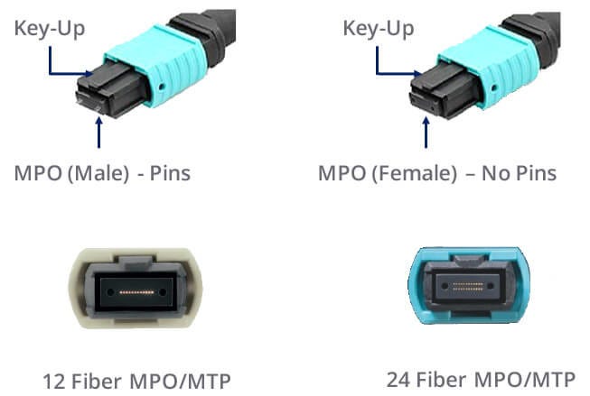
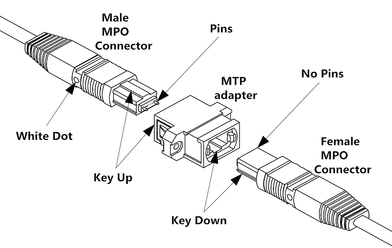
MTP/MPO connectors are pin and socket connectors-requiring a male side and a female side. Cassettes and hydra cable assemblies are typically manufactured with a male (pinned) connector. Trunk cable assemblies typically support a female (unpinned) connector. The connectors are also keyed to ensure that proper end face orientation occurs during the mating process.
Functions of MTP vs MPO Connectivity in 40/100G Network
The widely used 10G system generally would utilize a single MTP/MPO (12 Fiber) connector between the 2 switches. Modules are placed on the end of the MPO connector to transition from an MPO connector to a 12 Fiber breakout LC duplex or SC duplex cable assembly. This enables connectivity to the switch. 40G and 100G systems require a slightly different configuration.
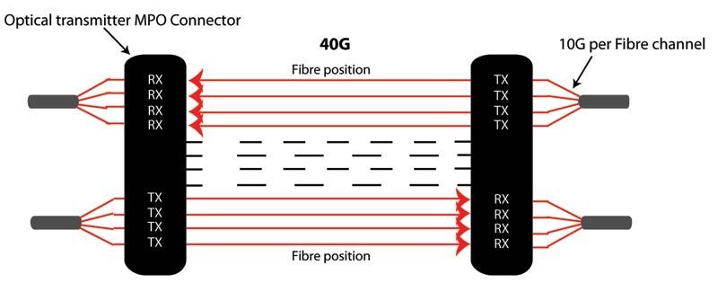
In 40G MPO connectivity system, an MPO connector (12 Fiber) is used. 10G is sent along each channel/fiber strand in a send and receive direction. This “lights up” 8 of the 12 fibers providing 40G parallel transmission.
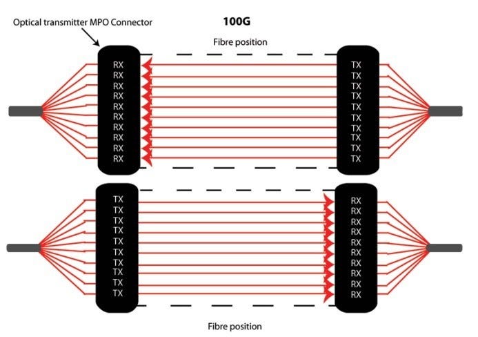
For optical 100G MPO connectivity system, an MPO connector (24 Fiber) is used (or alternatively 2 x 12F MPO Connector). 10G is sent along each channel/fiber strand in a send and receive direction. This “lights up” 20 of the 24 fibers providing 100G parallel transmission.
MTP vs MPO Connectivity Components
Along with MTP/MPO connector, there are some other MPO components that used in high-density network interconnection. In essence, part of the MTP/MPO connectivity solution is a variety of fiber optic cabling components. Generally, there are two types of cables used in this solution:
One is a standard MTP trunk which has an MTP/MPO connector on either end of a 12 or 24 fiber ribbon cable. The connector construction can vary to the point where the 24 fibers are terminated into a single MTP/MPO connector, or they can be terminated into 2 separate 12 fiber MTP/MPO connectors.
Another option used in this cabling configuration is an MTP/MPO breakout cable. This cable has an MTP/MPO connector on one end while the other end of the cable can have a variety of standard optical interfaces such as LC or SC connectors.
Moreover, these can connect directly into patch panels, MTP cassettes, and active equipment. The MTP/MPO cassettes provide a central patching and fiber optic breakout point where the MTP interface can be changed to SC or LC type interface. MTP/MPO cassettes are typically housed in a patch panel or fiber storage tray.
Conclusion
In summary, MTP vs MPO connectivity solution has proven to be an effective, feasible and flexible option to achieve 40/100G transmission, especially with the case of large- capacity and high-density data center environment. Not to mention that it also provides a reliable alternative for quickly connecting and rapid deployment. Hope the information offered in this article could at least help you understand this connectivity method.
More information about HTFuture’s MTP MPO is available by emailing Ivy: sales6@htfuture.com
Skype: live:sales6_1683
Related Product
(1) Optical module (1.25G SFP, 10G XFP, SFP , CWDM/DWDM, BIDI, 25G, 40G, 100G Module etc),
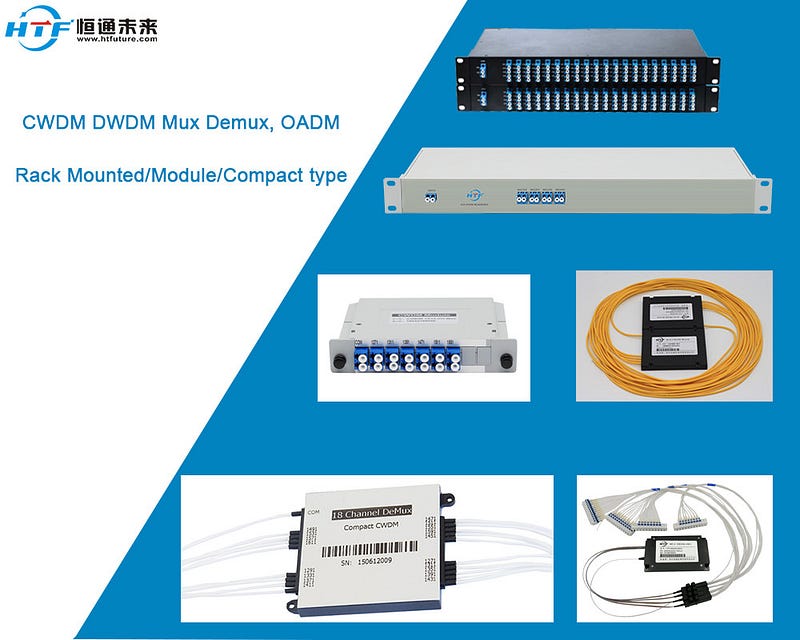
(2) Wavelength division multiplexer (WDM/CWDM/DWDM/OADM)
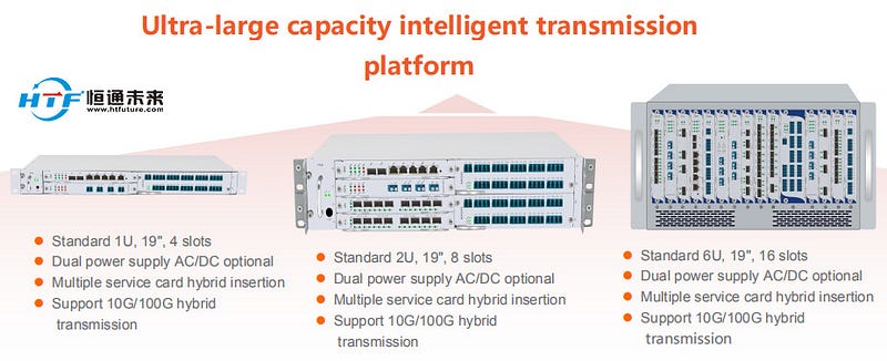
(3) Optical Transport Network Product (OEO, OTU, OBP, OLP, EDFA etc)